 JP Gleyzes
14 years ago I built my own CNC machine. At that time, CNC were running with Xp PC using parallel port. Gcode eaten by Mach3 software and sent to steppers controller board using the parallel port pins.
This machine, although dusty and rusty, still runs on an old PC... but it is time to design something more up to date.
This project is how I reused most of my setup and simply replaced Mach3 (and the old PC) by a modern laptop, controlling a FluidNC (GRBL) board via USB.
CNC parallel port control boards
Mach3, EMC2 and most of CNC softwares were using the parallel port in an (almost) standardized way. They all were outputing step and dir signals to control stepper motors directly on the port using 5v TTL logic.
Typically here is the wiring diagram of one of these control boards:
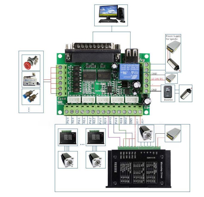
So all the control signals were sent to the parallel port and configured under Mach3 software.
My control board followed these guidelines and more specifically this wiring scheme:
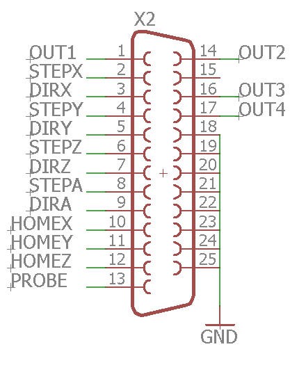
It is thus a board with the following specifications:
- able to drive 4 axis steppers (X, Y, Z and A)
- able to control 4 more outputs (Out1, 2, 3 and 4)
- able to read 3 home switches (HomeX, Y and Z)
- able to read one probe
This board should be generic enough to fit most (not to say all) "parrallel port" CNC controllers.
Converting my CNC control board to FluidNC
To design a "pass though" board from FluidNC to my control board I needed to "open" my board to check the logic interface after the parallel port.
Here are the schematics:
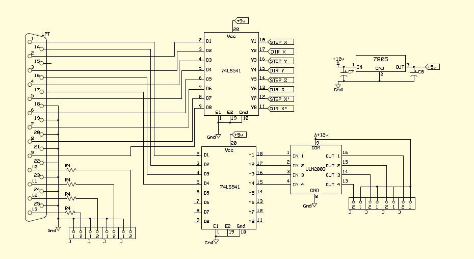
You recognize the parallel port (left) followed by 74LS541 chips. These chips are octal buffers and line drivers which are used to "clean" the step, dir and out signals coming from the parallel port. Perfect, if I input 3.3V logic signal instead of 5V one it will work thanks to these drivers!
And the outputs of this board (home signals + probe) are simple switches with a 420 Ohm resistor (named R4).
So nothing complex!
The FluidNC control board
The idea is thus to replace Mach3 software by an ESP32 on which will be flashed FluidNC/GRBL firmware.
Then this board will be connected to the parallel port connector of my old Mach3 controller board. This old board will thus be converted to a modern USB/GRBL/control board. (but could still work using the parallel port as nothing will be modified)
And trust me the new interface board cannot be simpler!
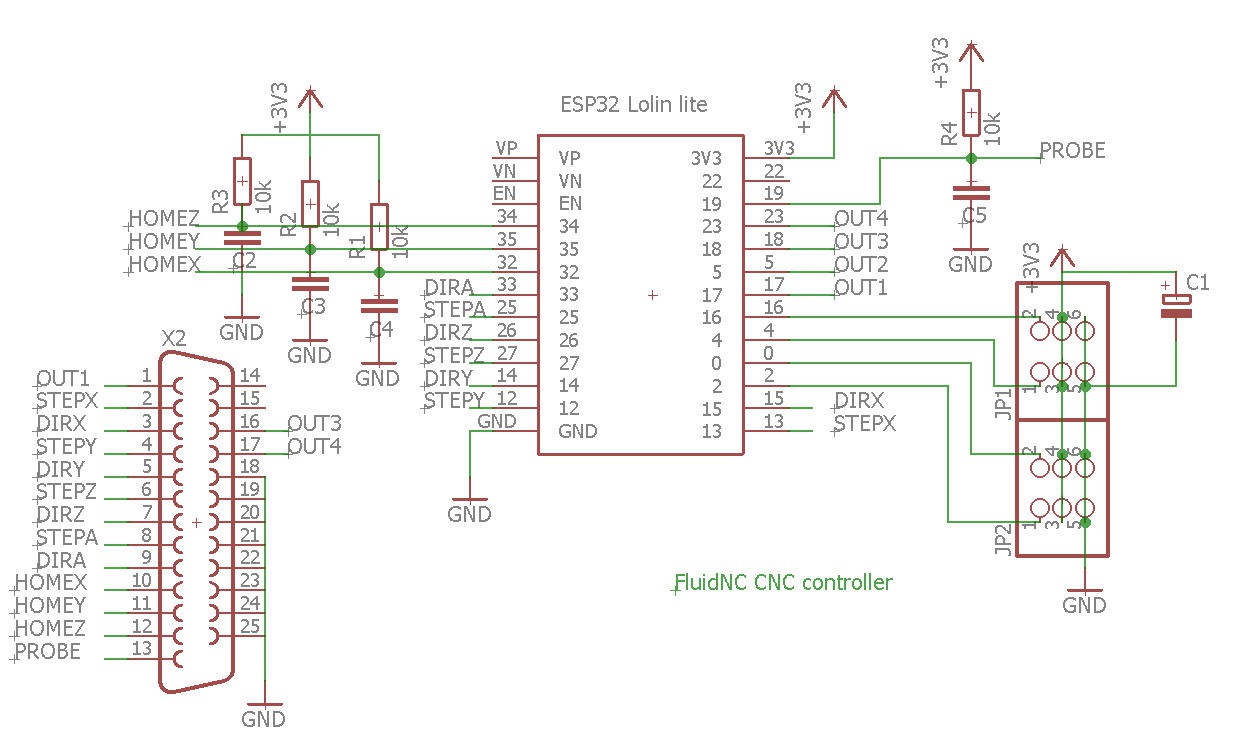
As you can see this board is almost empty! The only added electronics are 4 pull up resistors + capacitors on the "home/probe" lines.
They form RC filtering to debounce the inputs. And trust me these RC filters are more than useful. See here for details : http://wiki.fluidnc.com/en/support/controller_design_guidelines
So I chose R = 10k and C = 100nF to have a RC time constant close to 10ms.
And that's it, the ESP32 does all the rest with FluidNC.
PCB
The PCB was produced and kindly sponsored by PCBWay.
Here is a little video to explain everything!
Follow this log to get more information about how to order your PCB
Eagle files and Bill of Material are available here : eagle files and BoM
FluidNC installation and configuration
Installing FluidNC is fairly easy. Follow this log
Once done and your config.yaml installed you should be able to run your controller.
But let's have a closer look at this config file:
name: CNC
start:
  must_home: false
axes:
  x:
    steps_per_mm: 80
    max_rate_mm_per_min: 4000
    acceleration_mm_per_sec2: 100
    max_travel_mm: 1000
    motor0:
      limit_all_pin: NO_PIN
      limit_neg_pin: NO_PIN
      limit_pos_pin: NO_PIN
      hard_limits: false
      pulloff_mm: 1
      standard_stepper:
        step_pin: gpio.13:pu
        direction_pin: gpio.15:pu
        disable_pin: NO_PIN
  y:
    steps_per_mm: 80
    max_rate_mm_per_min: 4000
    acceleration_mm_per_sec2: 100
    max_travel_mm: 1000
    motor0:
      limit_all_pin: NO_PIN
      limit_neg_pin: NO_PIN
      limit_pos_pin: NO_PIN
      hard_limits: false
      pulloff_mm: 1
      standard_stepper:
        step_pin: gpio.12:pu
        direction_pin: gpio.14:pu:low
        disable_pin: NO_PIN
  z:
    steps_per_mm: 80
    max_rate_mm_per_min: 1000
    acceleration_mm_per_sec2: 50
    max_travel_mm: 300
    motor0:
      limit_all_pin: gpio.34
      limit_neg_pin: NO_PIN
      limit_pos_pin: NO_PIN
      hard_limits: true
      pulloff_mm: 1
      standard_stepper:
        step_pin: gpio.27:pu
        direction_pin: gpio.26:pu
        disable_pin: NO_PIN
stepping:
  engine: RMT
  idle_ms: 250
  pulse_us: 4
  dir_delay_us: 0
  disable_delay_us: 0
user_outputs:
  digital0_pin: NO_PIN
  digital1_pin: NO_PIN
  digital2_pin: NO_PIN
  digital3_pin: NO_PIN
It's a very basic configuration with 3 axis X, Y and Z. Speeds and accelerations have been tuned for my CNC.
All the limit switches are wired in parrallel so only the Z axis is defined with a hard limit. But X and Y switches will trigger Z instead !
Testing the board
Here is a very first test of this board with my vintage homemade CNC
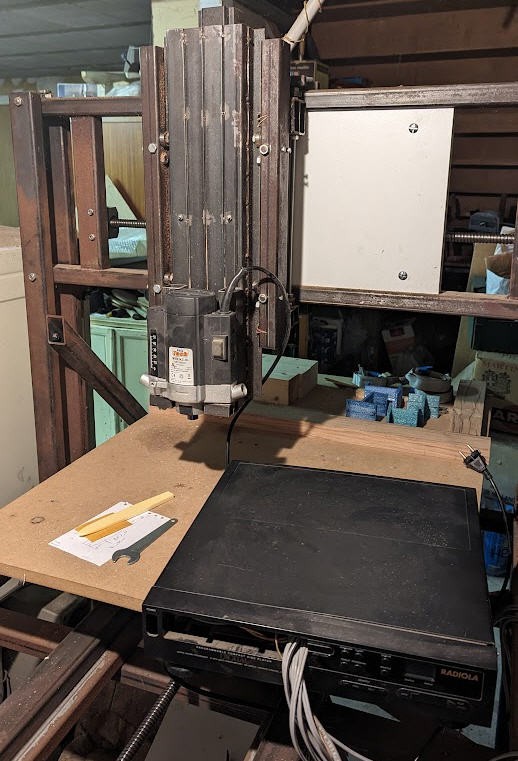
It's dusty and rusty but it works now with FluidNC!
Installing and running UGS
As shown in the previous video Universal Gcode Sender works seamlessly with FluidNC.
To install it, simply follow the download link, then select your configuration and install.
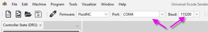
Then all you have to do is select your FluidNC board which should be connected to your computer with an USB cable. (Note that this USB cable is by default the way I chose to power my FluidNC controller board)
choose the right COM port and 115200 bauds speed
And you are ready to go!
The configuration of your FluidNC board is automatically got from the firmware. You can jog your CNC immediatly.
Note that UGS implements the "continuous jog mode" of FluidNC. As long you keep the mouse pressed, jogging will go on. It's such a great feature!
If you want to use NUM keypad to jog your CNC you will have to configure "keyMaps"
Go to the "Machine/Edit Macros" menu. Then select "keyMap" button in the top line.
Then you can change keys for jogging. Here is my set up:
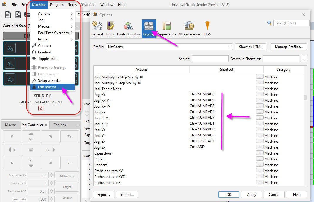
So Ctrl + NUMkey will jog the CNC. Continuous jog mode works as well with keys. A long as you keep key pressed, jog will go on.
When done you can export/import your preferences. So here are my preferences files!
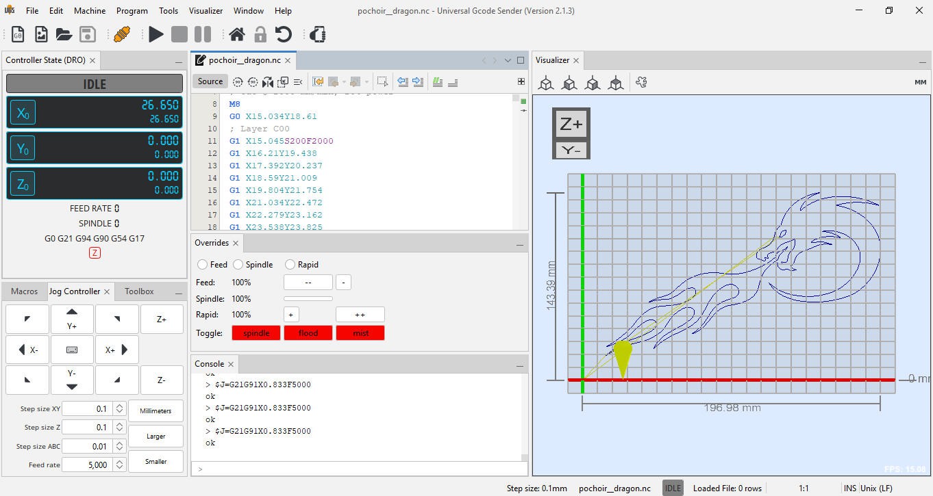
And finally, screen is totally configurable. So you can customize it to your needs!
On my side, as I wanted to mimick Mach3 software I wanted these features:
- seeing gcode synchronized with motion and path (on screen) (Vizualizer window right)
- zeroing the axis to fix origin of work anywhere in my machine (DRO top left window)
- overidding the DRO to adjust feedrate (Overrides window in the middle)
- jogging (while key is pressed) (jog controller + NUMpad)
- seeing what is FluidNC doing (Console windows middle bottom)
Enjoy FluidNC + UGS. Possibiliities are endless : I definitively stop using Mach3 for this opensource solution that I already love.
Adding a 4th axis to my CNC
I wanted to add a rotary axis to my CNC. This has been very easy thanks to the flexibility of FluidNC.
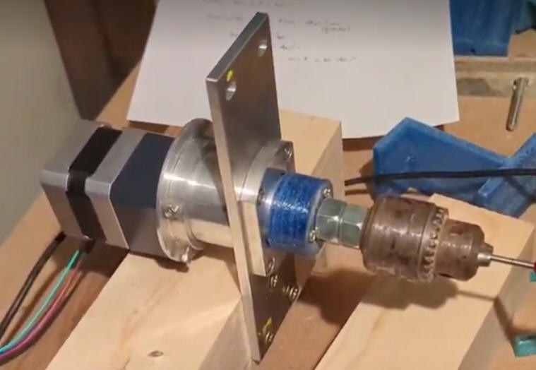
A very crude mechanics was built around a NEMA17 stepper equiped with a reducer 36:1.
Then you simply have to configure the rotary axis on FluidNC and UGS.
FluidNC
Here is the description of the rotary axis into the config.yaml file:
 a:
    steps_per_mm: 320
    max_rate_mm_per_min: 4000
    acceleration_mm_per_sec2: 200
    max_travel_mm: 100000
    motor0:
      limit_all_pin: NO_PIN
      limit_neg_pin: NO_PIN
      limit_pos_pin: NO_PIN
      hard_limits: false
      pulloff_mm: 1
      standard_stepper:
        step_pin: gpio.25:pu
        direction_pin: gpio.33:pu
        disable_pin: NO_PIN
My motor being a 200 steps per revolution with 16 microsteps and 36:1 reducer we get the magic number of "steps_per_mm"... that we have to understand as "steps_per_degree".
- One full revolution is 360°
- so 360° = 200 * 16 * 36 = 115200 steps
- so 1° = 15200 / 360 = 320 = "steps_per_mm"
And that's it. Tune max rate and acceleration, choose a very long max_travel_mm (as you basically have no limit), and you are gone!
UGS
Now open UGS and enable the A rotary axis
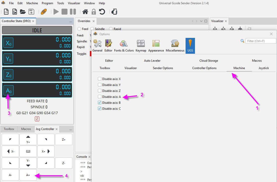
- Open "machine/edit macros/UGS/Machine" menu
- uncheck "Disable axis A"
- now your A axis will appear (you may have to relaunch UGS and reconnect your board)
- and you can jog your rotary axis (values in degrees)