 Marek
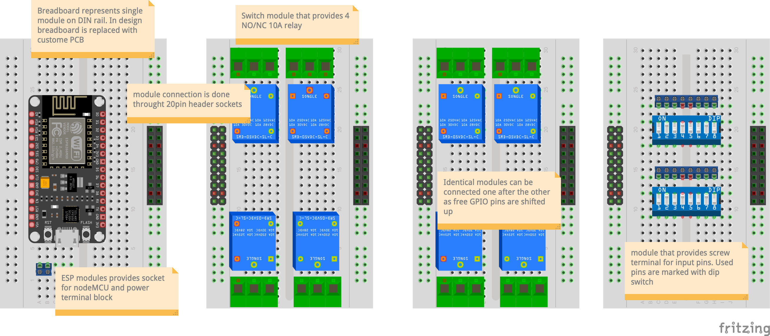
MarekSystem is design in modular way. Each module is mounted on DIN rail and connected one to the other with terminal block. First module contains ESP32 which is "CPU" of the whole block. Each next module is consuming GPIO from previous and shifting "free" pins back to the top. In this way identical modules can connect one to the other and use free pins.
Basic system is presented at this diagram:
Terminal block specification:
1: GND
2-17: GPIO
18: SDA (I2C)
19: SCL (I2C)
20: VCC
In this way 16 GPIO are provided between modules as well as I2C line that can be used to extend system with additional GPIO or advanced functionality (voltage, current, power, etc.).
Switch module consist of 4 10A relay blocks and fit into 2M (18mm*2) space. Four GPIO pins are consumed by each module leaving N-4 pins, where N is the number of initial pins to the next modules.
This module provide a possibility to control 4 230V inputs. As each relay has open and close channel it allows also to control curtain motors which cannot get both mains simultaneously. This can be realised by connecting zero output to input of the second relay.
Initial schematic of the module:

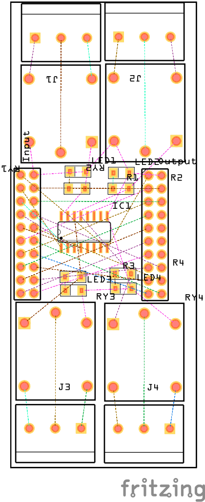
First version of PCB:
Feel free to ask any questions in the comments.
Discussions
Become a Hackaday.io Member
Create an account to leave a comment. Already have an account? Log In.