 Marek
MarekI am exited to share that PCB for first three modules are right now under production by PCBWay.
ESP Board
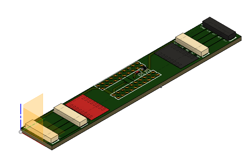
First module is simple ESP32 board that can take 32 pind ESPDevboard like that:
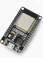
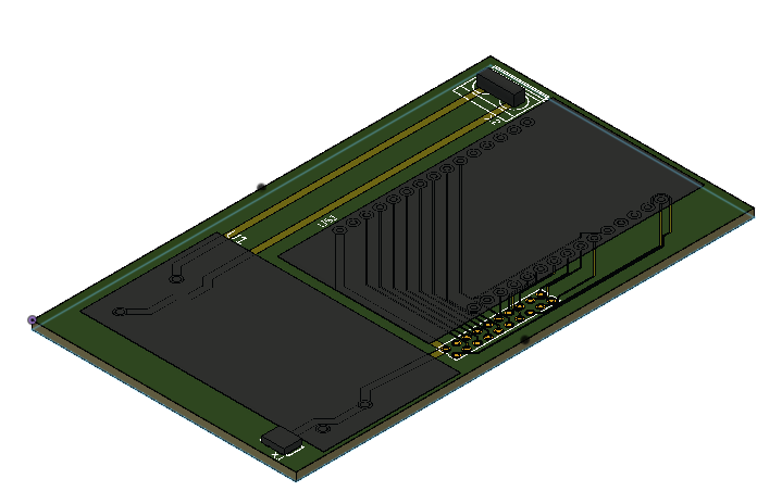
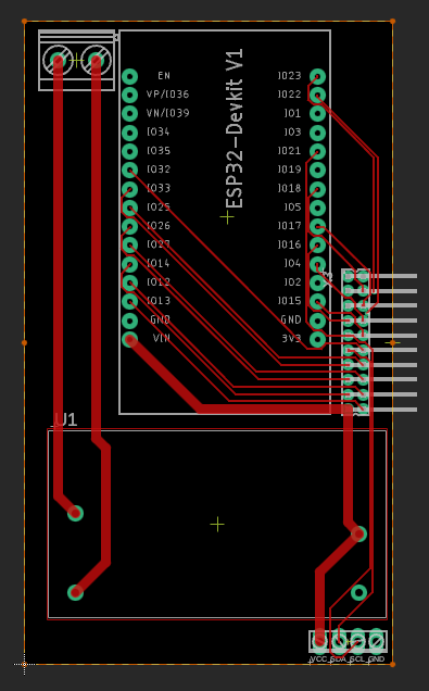
and expose 16 GPIO pins as well as I2C line through EasyLink system to rest of the modules. As mounted flat this board already takes some space also integrated 230V/ 5V power supply can be soldered and used so there is no need for any external power supply.
However this board also provide an option of screwing VCC and GND from any external source as well as I2C line if it is needed.
Board suppose to build very simple as complexity of handling of ESP32 lays inside devboard already.
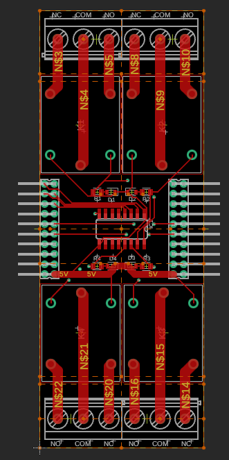
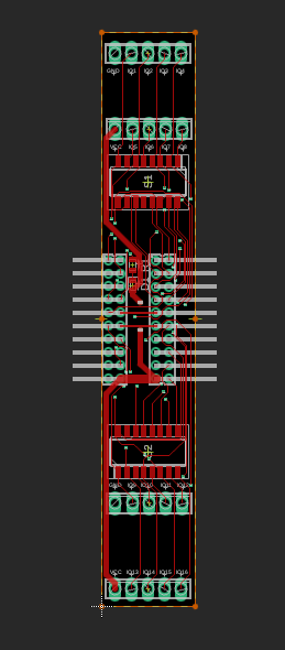
4ch Relay
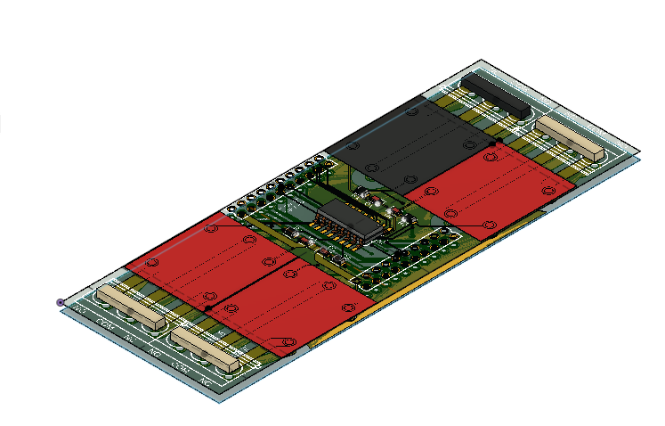
This module I have spend the most time on. FIrst it is the most complex one and involve handling significant amount of current as well as high voltage area.
PCB traces of relay main voltage are designed to handle 10A of current with temperature rise of 25C over the ambient temperature with only 1oz thickness. This is theory that you can get from many calculators like that: https://www.pcbway.com/pcb_prototype/trace-width-calculator.html. That is also something that I am quite interested to check with thermal camera on my prototype. Anyways if you are handling main voltage please be very careful as there is many considerations on the way and I am not an expert in this area whatsoever.
This modules takes EasyLink connection and uses first four GPIO pins shifting remains 12 on output side for other modules. That means that single ESP Board can drive 4 such modules connected in series or 2 such modules and still 8 GPIO remains for other modules. I am thinking about some I2C GPIO pin extension module to break it limit but first let's confirm base modules working.
Terminal Block
Last module is just screw terminal block connector compatible with our EasyLink system.
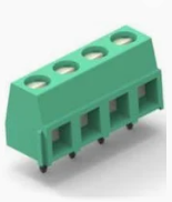
Thanks to mounting 4 blocks with 5 position each I am able to securely attach 16 general input/output pins and on remains four position that is 2 time GND and 2 time VCC. In this way I hope to deliver secure and reliable connection to switches and buttons that are external to our line.
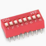
As this module can be mounted in any position of our EasyLink line each GPIO has a switch to detach it from passing it to the following module. It is realised by DIP switch that can be turned on and off.
PCB is design to fit into standard 1M size DIN mounted case.
Once again thank you PCBWay for sponsoring first production and looking forward to soldering.
Discussions
Become a Hackaday.io Member
Create an account to leave a comment. Already have an account? Log In.