 mkdxdx
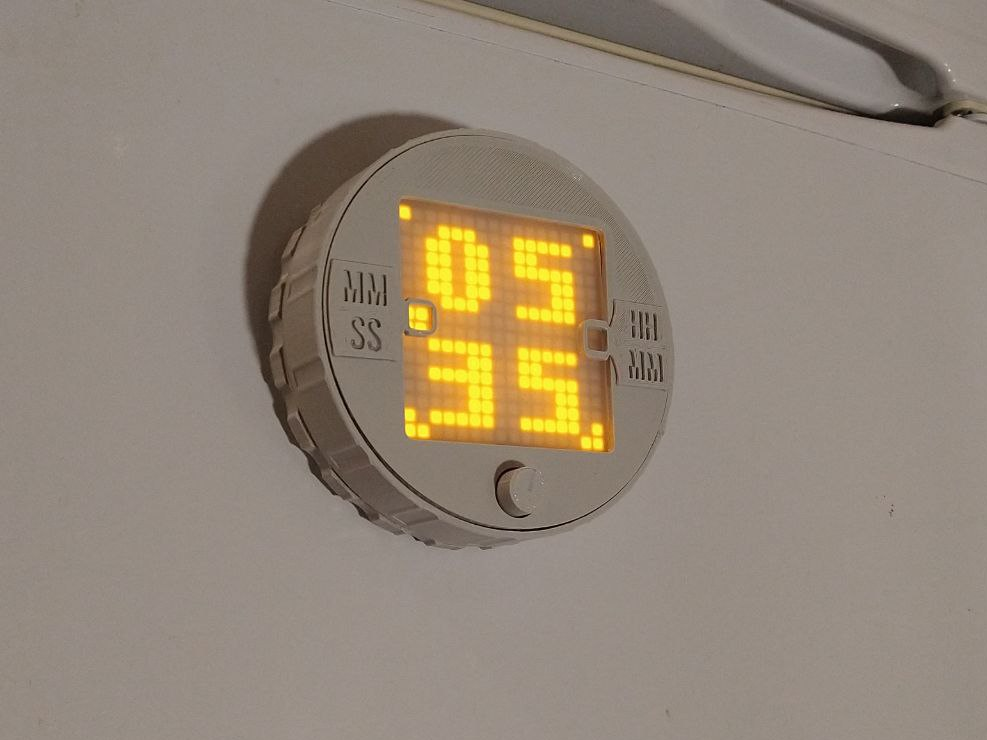
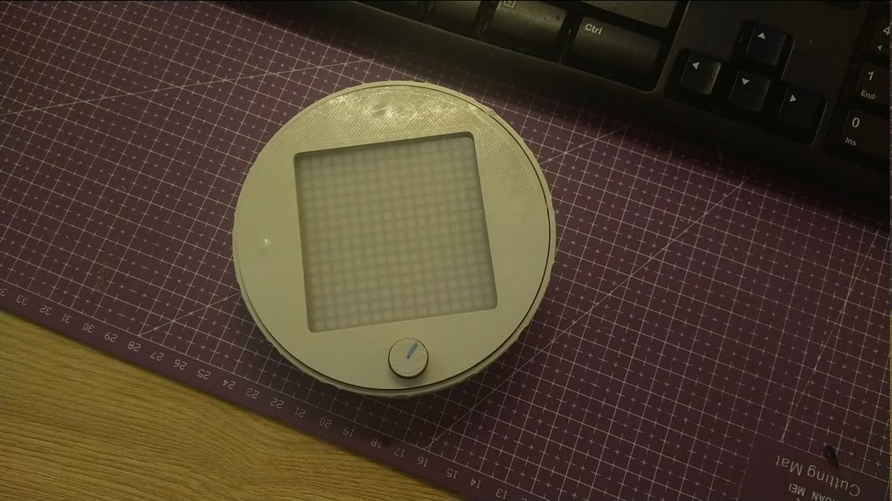
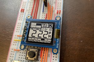
Rotate the dial to set the time, push the button to start countdown. Once time is out, a beep will sound, push the button again to shut it.
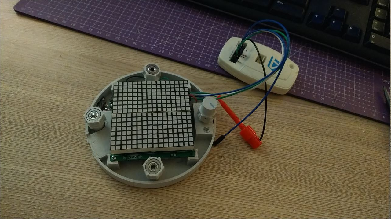
Time is displayed on 4 8x8 LED matrices driven by MAX7219 on my own quad module for DIP driver version.
Able to count down from 24 hours, but precision will probably be off by a few seconds due to not using a precise timing source.
Uses:
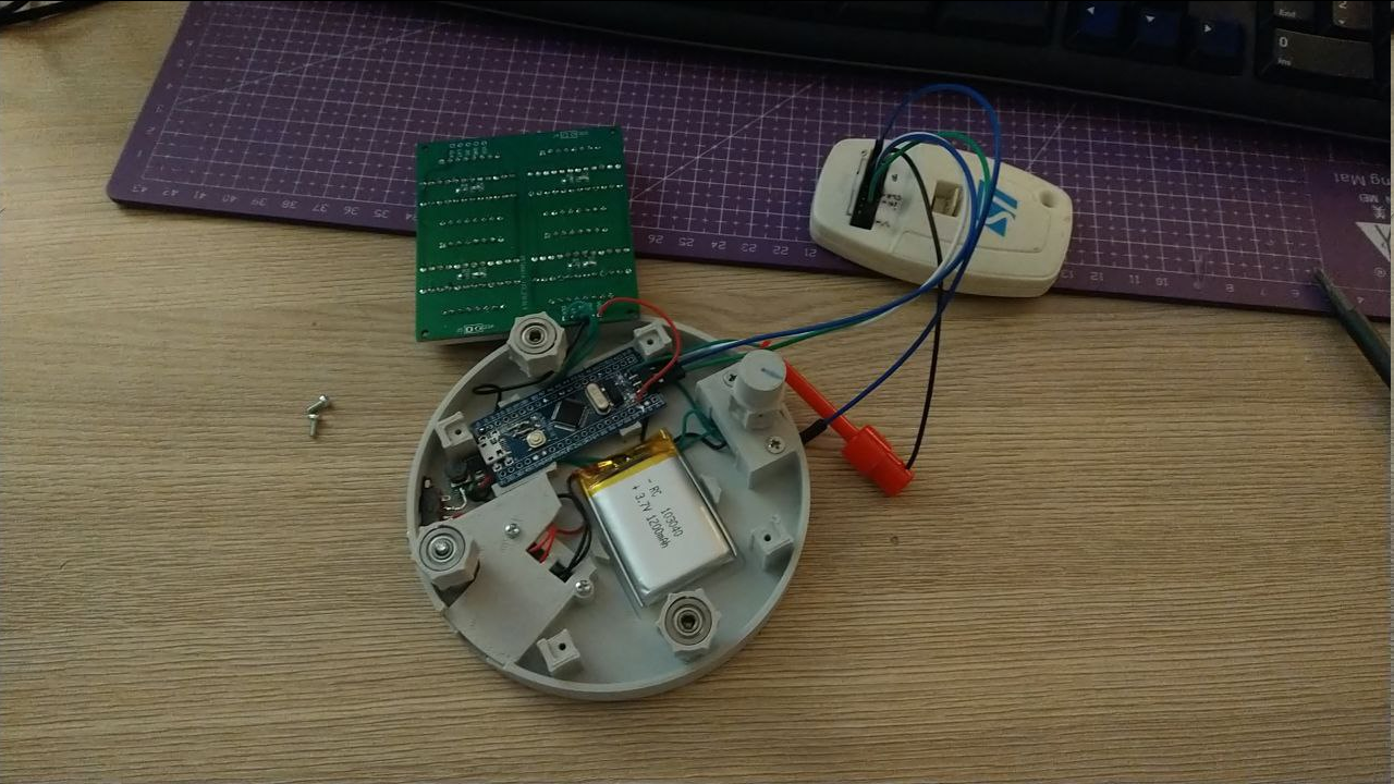
- STM32F103 "blue pill" for brains;
- TP4056 (+ protection IC onboard) to charge a 1200mAh lithium battery,
- A boost converter to pull the voltage to 5V to properly power LEDs.
- An encoder with push contact for control.
A little 8ohm loudspeaker driven by MCU PWM and amplifier circuit (to be designed) to create buzz.- An active buzzer to alert everyone in nearest vicinity that time is up.
More in logs.
 I've ditched the idea to use PWM to generate sounds in favor of an active buzzer, buzz of which is modulated by the same PWM, albeit at around 2Hz to mimic a fire alarm. I think there is no chance i could achieve the same loudness as these little fellas can do - not with simple schematics atleast, you would need a bridge driver to push the aler further than a few rooms.
 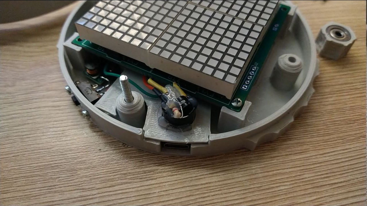 A new addition - instead of 6 weak magnets to attach the timer to fridge door, I've decided to use 4x 18x3mm neodymium magnets, each providing around 2,5kg of force. Enough to lock it in place and provide enough grip to rotate the dial without using another hand. Neat!
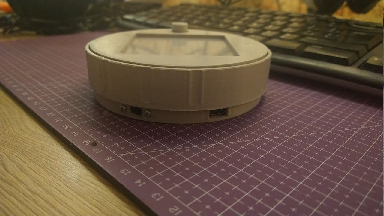
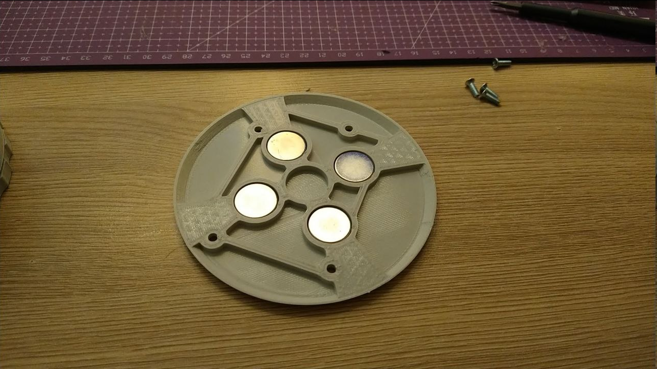 And to transfer the whole holding force to the primary case - it was redone to have recesses for heat set nuts, because threading plastic will probably not work when there is so much force pulling it in other direction.
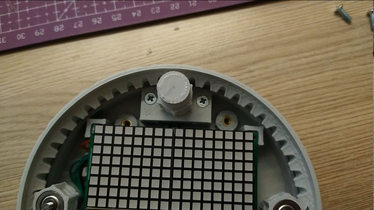 And boom, there it is.

 It does not have buzzer circuit though, I'm still waiting for DC filter capacitors to arrive.
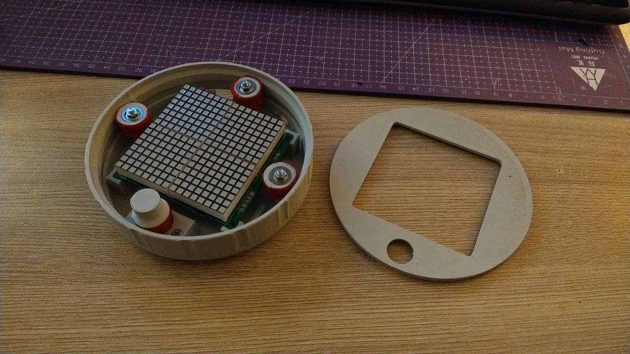
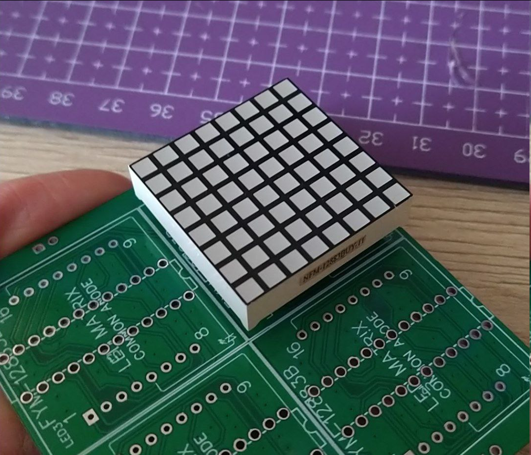 So, first i went to JLCPCB to design and fabricate several carrier modules - different versions, actually. I made 1x, 2x, 3x, 2x2, 3x2, 5 of each, just so I could reuse them later after this project also.
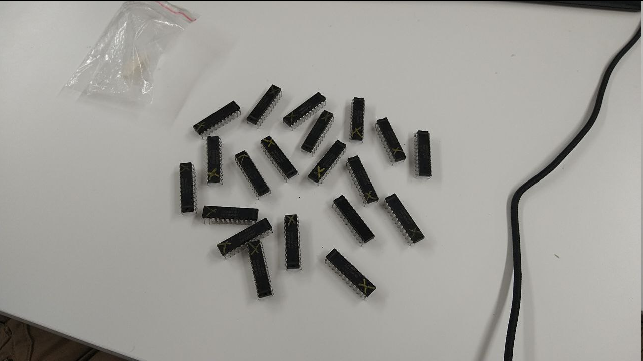 But module PCBs are already made, what do I do now? That's right - order some more LED drivers, because matrices won't drive themselves!
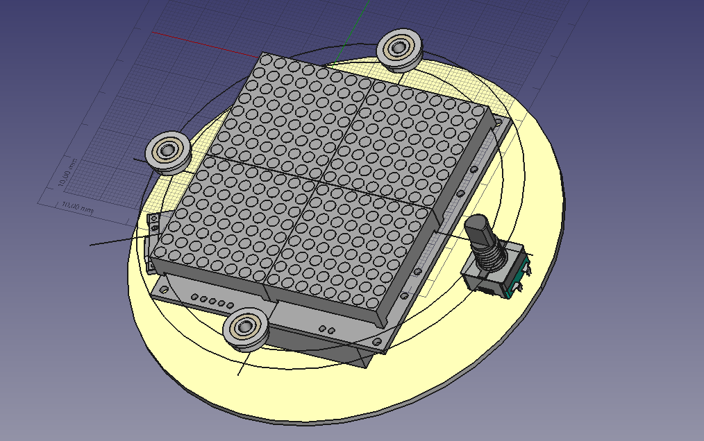


 Kinetic Labs
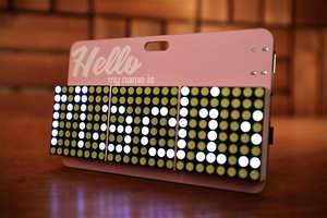
 Madison
 Mike Szczys
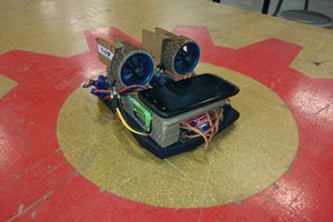
Hello. Very nice project. One question. What are the dimensions for the led matrix individual module?