 Wissam Tedros
the board is a 2-layer board that fits inside a standard RC servo housing, so no added volume to the overall RC servo, the original cables must be unsoldered and connected to the servo pads, to get position feedback, the POT must be connected to this board as well as the original servo controller.
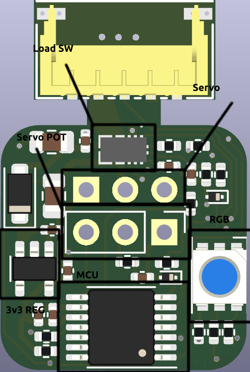
- The connector is a low profile Hirose DF65 5pin connector, where 4 wires are reserved for power delivery and 1 for the One-wire communication.
- an on-board regulator powers the micro-controller and the other ICs, the 3v3 on the POT pads is to sense the 3v3 of the original servo controller.
- the Load switch is controller by the micro-controller, to either power the servo or not, and gives an analog voltage proportional to the current drawn by the servo for torque feedback.
- the potentiometer provides position feedback.
- the RGB is connected to 3V3, the output voltage of the Load switch, and a GPIO of the MCU.
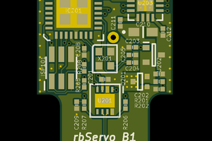
- on the bottom layer there are SWD pads to program the MCU with an ST-LINK
 RasmusB
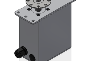
 patchartrand
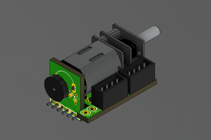
 Holotype Robotics
 bobricius