 mircemk
In practice, we very often need to measure low resistances. Measuring low-value resistances, especially those less than 1 ohm, is nearly impossible with a standard multimeter. On the other hand, an commercial milliohmmeter instrument is in the price range of several hundred dollars and is not cost effective for self builders.
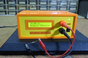
This time I will describe to you a simple and inexpensive way to make such an instrument, for the production of which we will not need more than a few dollars. With this instrument we can measure the resistance of 0.001 Ohm or 1 milliom. The result is displayed on a 4-digit 7-segment display that is easy to read even at wide angles.

You can find the original project on the rcl-radio (http://rcl-radio.ru/?p=100859) page. Just to note that the code uses a modified STM32 library which has been modified by the author and is compatible with Arduino nano. The heart of the device is ADS1110 IC wich is a precision differential input analog-to-digital (A/D) converter with up to 16-bit resolution.
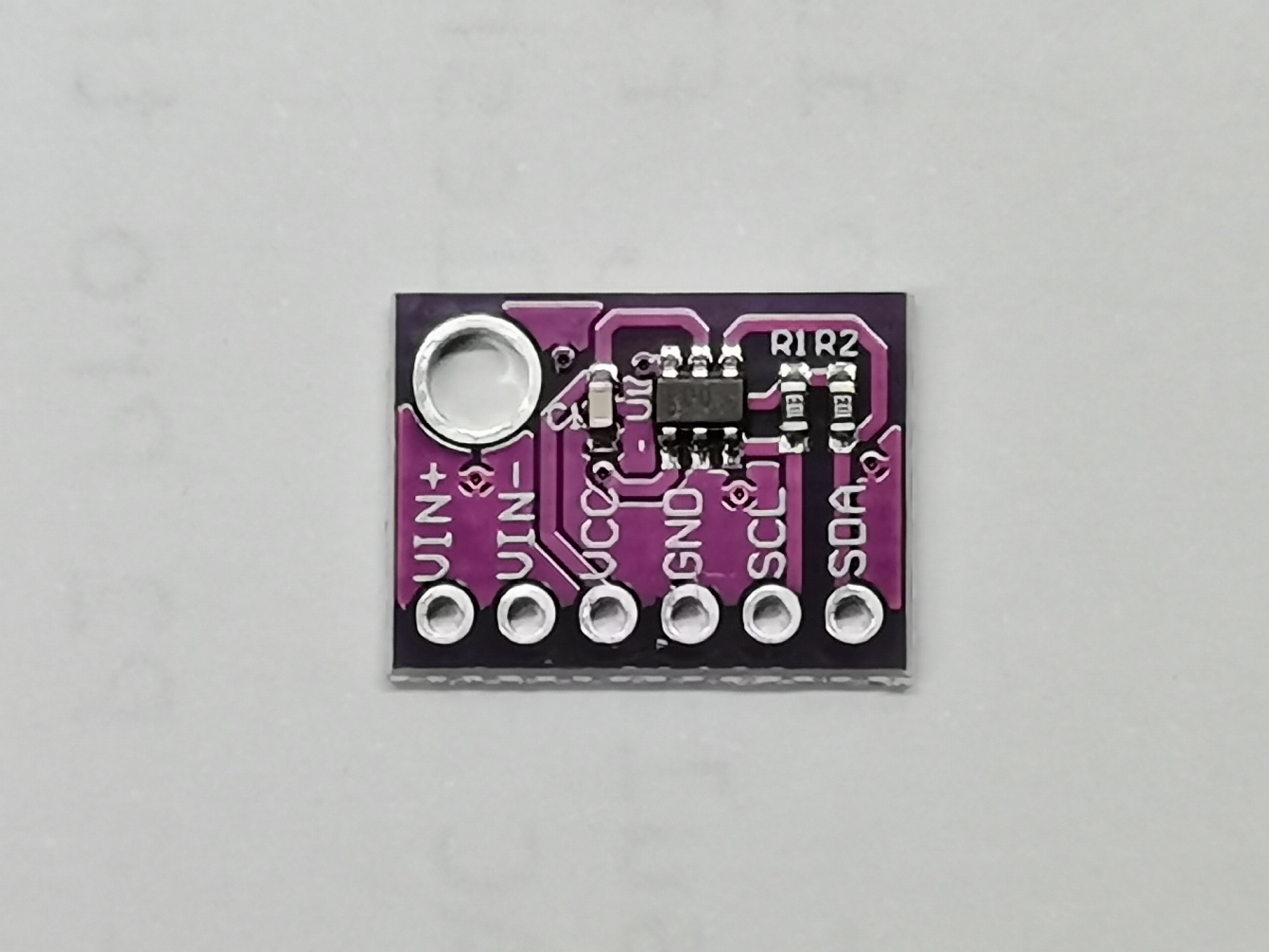
The ADS1110 uses an I2C interface to communicate with the microcontroller, and measures at 15, 30, 60, or 240 samples per second and has a built-in 1, 2, 4, 8 voltage amplifier. The measuring range is from 0 ohms to 150 ohms.
Otherwise, the device is very simple to build and consists of several components:
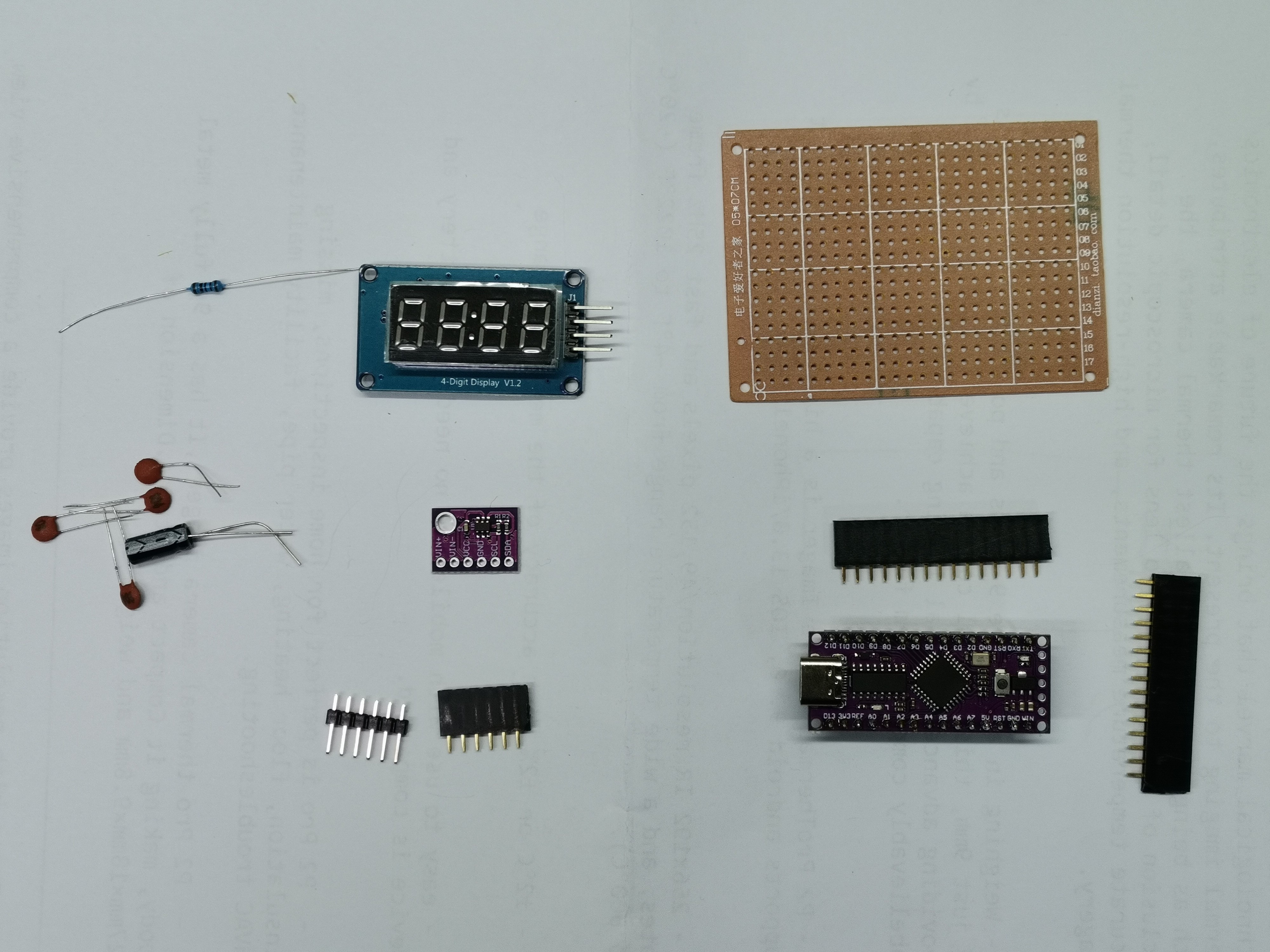
- Arduino Nano microcontroller (I am currently using a cheap version with LGT8F328P MCU)
- ADS1110 A/D converter
- TM1637 4-digit 7-segment display
- and a few resistors and capacitors
This project is sponsored by PCBWay. They has all the services you need to create your project at the best price, whether is a scool project, or complex professional project. On PCBWay you can share your experiences, or get inspiration for your next project. They also provide completed Surface mount SMT PCB assemblY service at a best price, and ISO9001 quality control.

The measuring leads should be as short as possible, and they need to have the same length. To calibrate the milliohmmeter, you need to accurately measure the voltage of 3.3 V (supplied from the Arduino board) and indicate it in the line:
#define U33 3.342
The accuracy of the resistance measurement is directly dependent on the accuracy of the 100 ohm reference resistance and the accuracy of the 3.3 V voltage measurement.
And now let's see how the instrument works in real conditions.
Immediately after switching on, we need to prepare the measuring instrument. For that purpose тhe circuit uses a “0” button to calibrate the zero before measuring low-resistance resistances.

To calibrate the zero, you need to short-circuit the test leads and press the “0” button. Now let's make more measurements on resistors with different values between 0 and 100 Ohms.
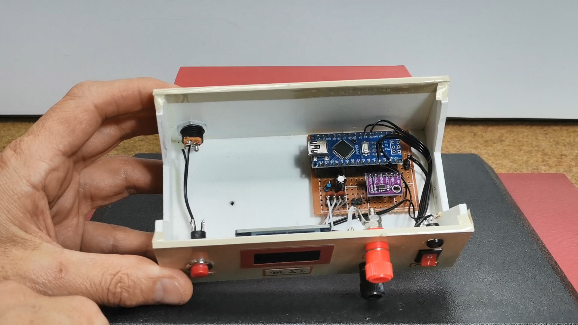
Finally, a short conclusion. This is an indispensable and very useful instrument for any laboratory, especially considering the fact that it is very inexpensive, and we can make it ourselves. The device is installed in a suitable box made of PVC board with thicknesses of 3 and 5 mm and covered with self-adhesive colored wallpaper. I would like to emphasize that it is preferable to power the instrument from an external stable voltage source for greater accuracy.


 Jim Heaney
The circuit schematic (including the Ru schematic) shows a 100uF capacitor, but the component list shows 1 x 10uF capacitor. Which is correct?