 Sean Francis N.
CONTEXT
For a while now, I haven't been able to create a project outside of college. Due to the December break that had just passed, I was able to think of a weekend project (which actually took me three weekends due to several reasons) when I first saw a solar garden light that one of my neighbors had in their garden. And I thought, what if I make one that serves as both a flashlight and desk lamp? As such, I decided to act on that idea. It was perfect timing as well, as I recently received a 3D printer on Christmas day, which was something I've always wished for (thanks mom and dad :>). And so, it was time to design my project, The Companion Light. Let this section of the project serve as a guide if you ever want to make your own.
Note: This project's PCB is a prototype, I will be creating a professionally-designed PCB for it in a future update.
ELECTRONIC DESIGN AND CONCEPT

As with any device using an IC, I simply relied on the datasheet to provide me with an optimal way of implementing the circuit. The IC I used is called the YX8018, a cheap joule-thief IC commonly used in solar garden lights, the reason why I was inspired to create this project in the first place. The IC basically steps up a 1.2V input to create 3V at its output. Moreover, the inductor placed in between pins 1 and 4 induces a specific amount of current at the output depending on its value. I added a capacitor between input and ground to ensure enough voltage is entering the circuit. (Note: Check the designer's notes in the schematic and the references section for videos and datasheets on the YX8018.)
PROCESS
After calculating for the necessary components' values, I came up with a list of materials to put the circuit together:
Parts/Components:
(1) 1.5V 150mA Solar Cell
(1) 1N4001 Diode
(1) SPST Switch
(1) 1.2V 2Ah NiMH Battery
(1) 100 uH Inductor
(1) 0.1 uF Capacitor
(1) Straw Hat LED
(1) 1.2V Single Cell Battery Clip
(1) 3D-Printed Enclosure
(1) Protoboard (preferably small)
Jumper Wires
After gathering the components, I then proceeded to implementing the circuit in a breadboard without the solar panel, as all I needed to know at the time was whether or not the IC could actually provide enough current to the LED. And as expected, it did. I then proceeded to solder the components into a small prototyping board I cut from an old project. Upon testing, the circuit worked in a protoboard setting, using a 700 mAh rechargeable NiCd battery.


In the protoboard test, it can be seen that I am using an old 5V solar panel. However, I do not recommend using a 5V solar panel for this project in its permanent form. I merely used the 5V solar panel to see if it actually charges the IC. In its final iteration, my device ended up using a 1.5V solar panel, and even then, it is not recommended to keep the device under the sun for a long time. This will be explained further in the design limitations section of the project.
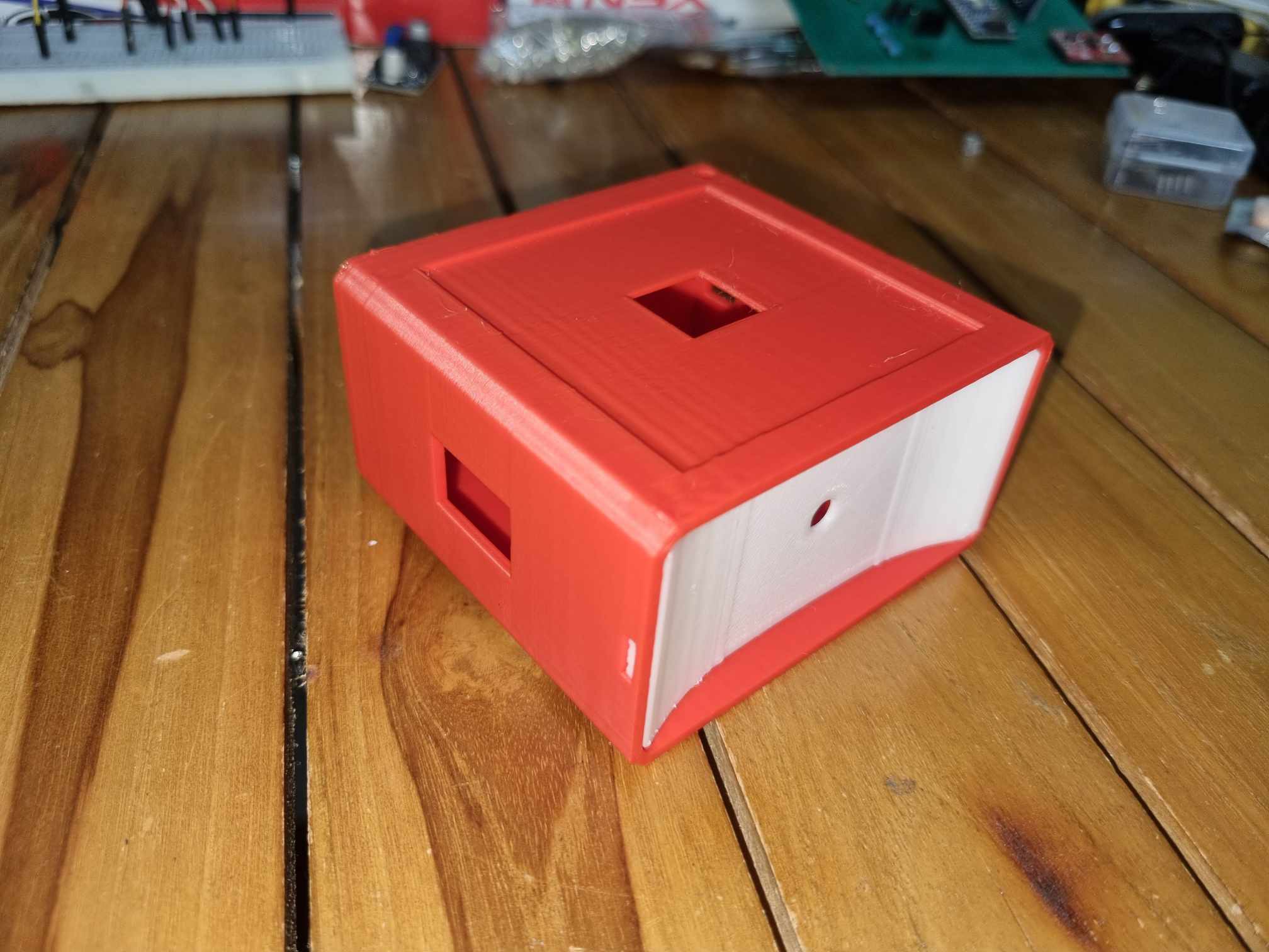
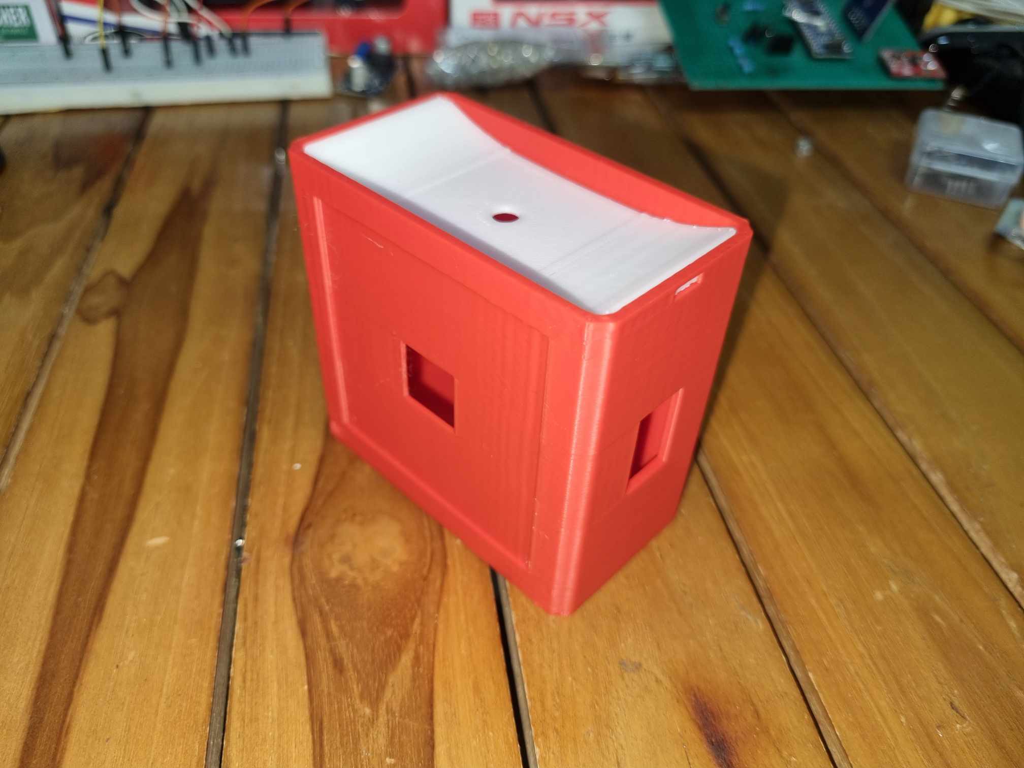
After assembling the electronics, I moved on with the structural side of the project. I proceeded to design a simple enclosure for the electronics. I designed it in such a way that it could be small enough to be handheld, contain the 1.5V solar panel, can reflect light more intensely (by spray painting the reflector in silver, which is seen in the output section), and potentially be hung on a keyring (by adding two small holes on the enclosure where the keyring or a string may pass through). I also printed it using PLA filament from eSun, with a 0.16mm printing resolution. The resulting enclosure is seen below:
OUTPUT
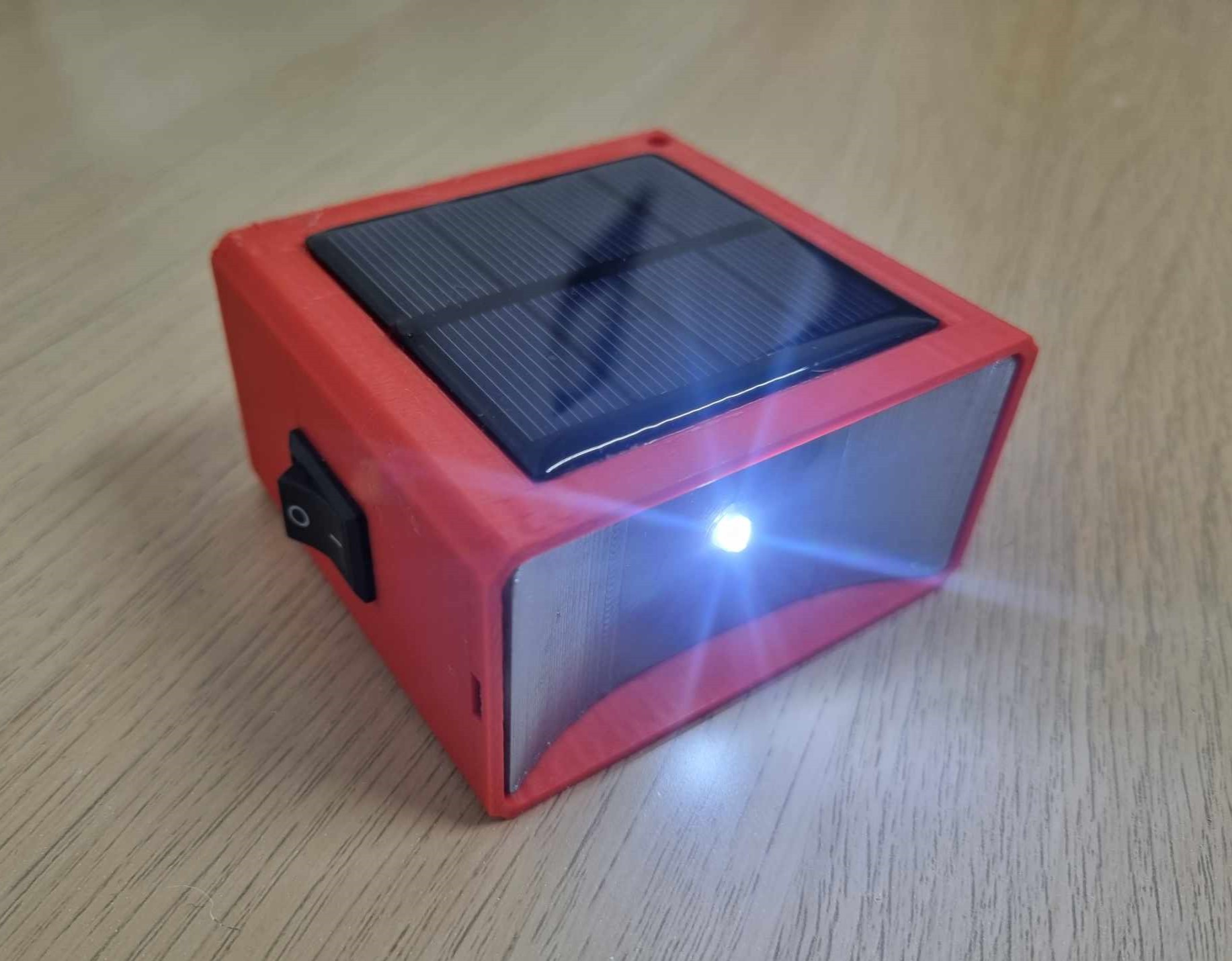
The Companion Light
To say the least, I was proud of my weekend project. Not only was I able to say confidently that I have gotten better with designing electronic circuits, but I was able to create something with utility. Furthermore, I also got to use my 3D printer to help bring my idea to life. It was working well! The amount of current passing through the LED was able to provide enough light to see within a short distance in the dark, albeit not being the most luminous of flashlights. To remedy it, I spray painted the reflector in silver, as it would help light spread more intensely. For its application, the enclosure was sturdy enough thanks to its dynamic printing resolution. This was how well it did while being pointed towards the wall of my room while the lights are turned off:
The Companion Light in action
Overall, I could say my project was a success! It is small enough to be handheld, had bright enough light to be used as utility, and was solar powered.
DESIGN LIMITATIONS
While it is proven the design works, it is still good to consider that it has its limitations, which may serve as points for improvement in future versions and other projects:
1.) Solar Charging Restriction - This application of the YX8018 assumes that the device will not always be under direct sunlight for solar charging. At 150mA, charging the NiMH battery beyond 13 hours may cause it to sustain damage, shortening the battery's shelf life. So, be careful when keeping it charged under direct sunlight;
2.) Light Intensity - While useful in short distances, it is not recommended to use it during emergency situations where safety is of utmost priority (project idea!). At best, this may be used as a tool for those whose work requires high precision;
REFERENCES
https://youtu.be/7TRyD_EXCbA
https://www.datasheet-pdf.info/entry/YX8018-Datasheet-YX8018-Solar-LED-driver
https://datasheetspdf.com/pdf/710956/Shiningic/YX8018/1
SPECIAL THANKS
To mom and dad for getting me a 3D printer for Christmas. You don't know how much you two inspire me to follow my passion for creating things every day. Thank you :>>
To the reader, for taking time to get this far down my project's details. To more projects soon!