 sky-guided
First Light accomplished. What did I learn?
The circuit in its current iteration,
1: gets hot alarmingly quickly
2: is trying to draw more power than I can actually supply.
Those seem related, yeah.
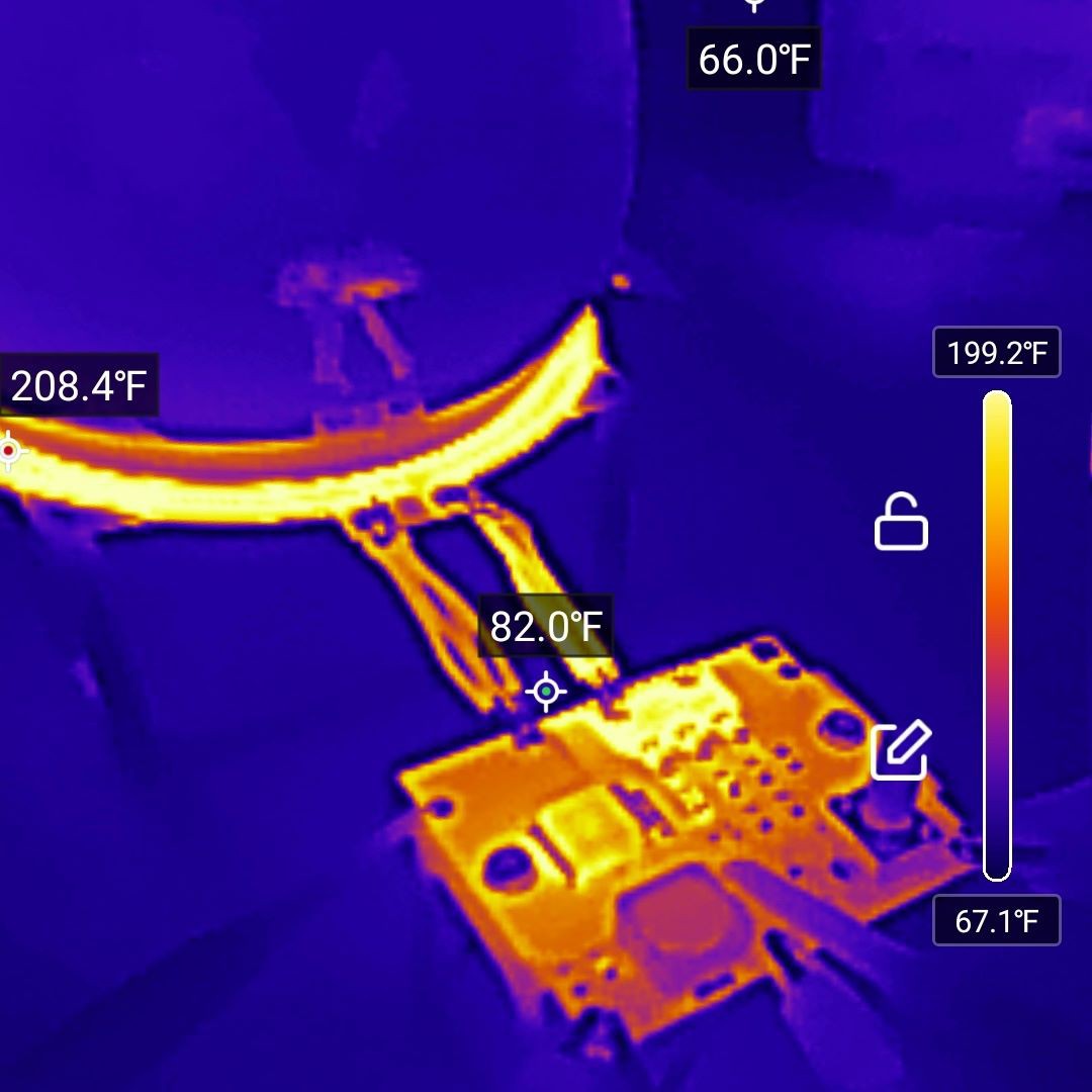
apologies for the excessively american temperature units
Based on simulating the circuit in the condition tested, at 15 volts supply I'd expect to see something like 50W power draw, at around 3.5A. The tests discussed in the previous post sure looked like the USB-based bench supply was badly voltage sagging, so the next day I hooked up the beefier bench supply -- and very quickly started sagging, then blew another mosfet. I suspect that this very-budget bench supply has some sort of destructively un-graceful switch from constant-voltage to the constant-current mode it failovers to when it hits 5A, but it's also entirely possible that the mosfet blew first and I saw the power supply feeding a shorted chip.
My power budget is <5A @20V (the 100-watt maximum of USB-C-PD), but I'd prefer to stay <60W if possible.
If I simulate a lower primary capacitance (e.g. 66pF instead of the as-built 99pF), power draw is dramatically greater and the higher resonating frequency is also a closer match to what I observed on the bench. Same thing if I sim a lower inductance value. (This relationship of LC values and frequency is of course exactly what you'd expect just from looking at the series LC equation, but the effects on power I hadn't thought ahead to anticipate.) Based on the cap data sheets I wouldn't expect a huge de-rating but who knows. It's also possible there was error in measuring inductance values -- I don't have an LCR meter, so I set up a little parallel LC circuit that I drove with a square wave and o-scoped the resultant ringing.
Takeaway: I can likely offset observed power-hungriness with either a higher-value capacitor bank or primary inductor.
Adding more capacitance is pretty easy, so that's my next step. I may also investigate making a four-turn PCB inductor, but I'd prefer the wide open traces of the two-turn (plus two-turn make it easier to route traces for the ionization pilot arc, which is a topic for future discussion).
On the topic of the PCB inductor getting super hot: based on sims I expected ~10 peak amps in the primary inductor, or maybe 12A at the very worst. PCB trace width calculators using IPC-2221 or -2152 thermal design guidelines predicted temperature rises of <30°C. I observed temperatures shooting past 130°C within about thirty seconds. Either I'm getting quite a bit more current than expected, or the thermal design formulae don't apply here.
If I plug numbers into the SaturnPCB Toolkit -- a load current of ten amps, an 8mm x 600mm 1-oz trace, and a frequency of 13MHz -- it tells me to expect a power dissipation of about 3.2 watts. One thing the formula doesn't consider is that the inductor coil has two conductors stacked on top of each other. I also notice the toolkit is only estimated 0.02Ω DC resistance, so of course if I scientific wild-ass guess an actual resistance of 0.2Ω I'd expect ten times as much heating. That's a better match for my sensibilities for how immediately cookin' things got.
On a more fundamental level though, if the device is overall drawing 50-60W, that energy clearly has to go somewhere. Physically I'm not sure where I should expect the balance of energy to go. There's gotta to be some combination of circuit waste heat, energy delivered to the plasma, and energy emitted as legally-dubious radio waves. I'd hoped that the latter two would be the majority, but that was based more on optimism than analysis.
In any case, I'm going to try to bring the overall power draw down first, then reevaluate where I'm at on the coil temperature. The few other examples I've seen of this project all use copper tube coils so it's always possible that a PCB coil just isn't viable, but I'm far from ready to give up.
The coil isn't the only thing heating up though! Reducing overall power might help, but there's more I can learn from the first v0.2 tests.
Managing heating in the capacitors can be addressed by adding more capacitors. If I use six caps instead of three, by the simple magic of P = I²R I should expect a quarter of the heating.
I couldn't find thermal specs for the TDK capacitors I've been using, but looking at Kemet design tool for the next-iteration caps, and, well
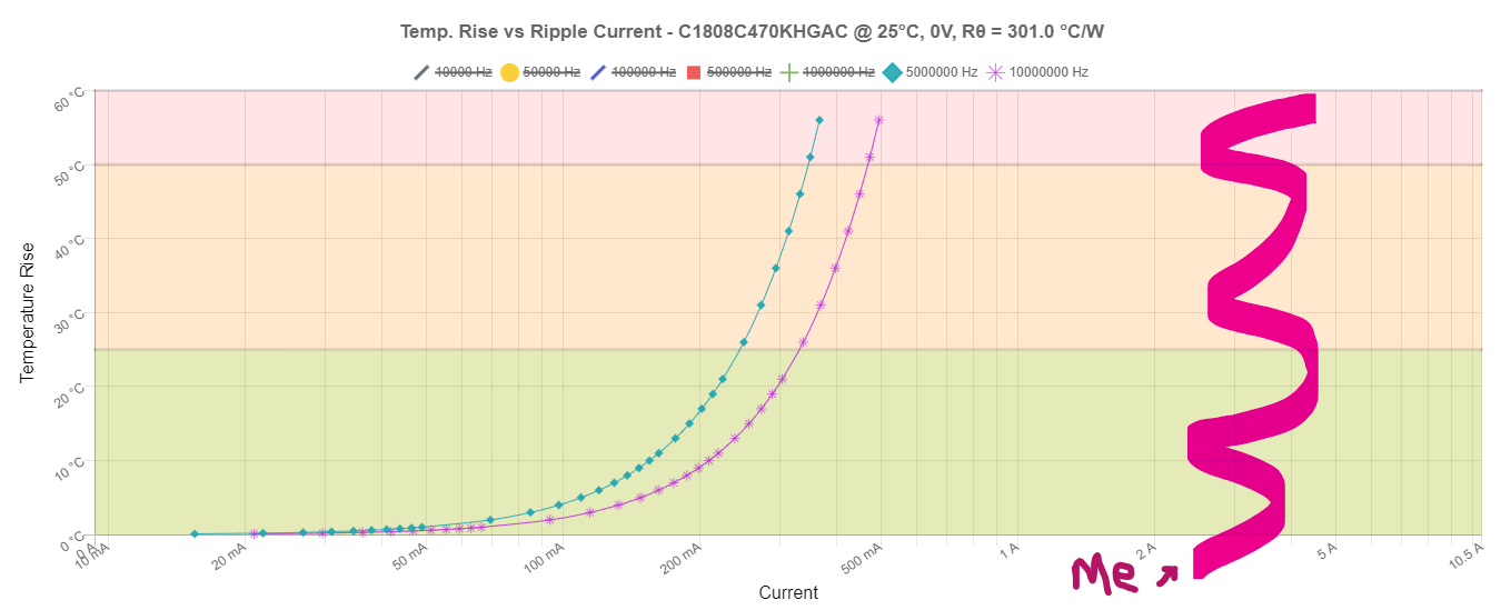
Yeah that aint' great. 301C°/W feels a bit pessimistic but I don't have enough intuition yet to really know.
For the next board revision I can also consider dropping some thermal vias towards the heatsink underneath, and/or using SMD thermal jumpers to suck heat towards the ground plane.
On the topic of the heatsink -- based on the thermal cam it definitely looked like the heatsink was getting toasty, which is a good sign for it being decently well coupled to the mosfet. However, after thinking about it for more than five seconds I realized that I really ought to be keeping the heatsink cool because an already hot heatsink can't sink heat.
I knew that a fully-passively-cooled driver circuit was likely overambitious but I wanted to give it a go. Looks like I may have to install a fan (and possibly a bigger heatsink) anyway.
Further experimentation will mean soldering on a new mosfet. That''ll require not only removing the heatsink, but also scraping off the phase-change thermal interface shmoo that's oozed all over the place only to squeeze into one thin layer for next tests. I've been putting that off for a few days, but it's gotta get done sometime.
Stay tuned, dear reader.
Discussions
Become a Hackaday.io Member
Create an account to leave a comment. Already have an account? Log In.