 sky-guided
Spent a big chunk of the weekend adjusting a variety of component values.
Here's the waveforms with the circuit unloaded (no toroid), at 18V supply:
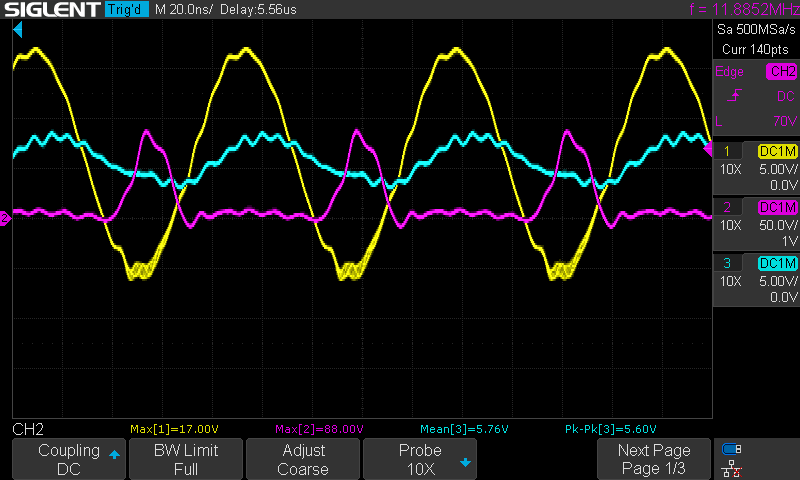
Yellow is Gate (5V/div), purple is Drain (50V/div), blue is feedback network bias input at TP5 (5V/div).
Looks decently healthy to me. I suspect that the gate protection zener diode is doing its job and helping to keep drive voltages within operational limits.
Here's the traces when the xenon is fully toroid-ing:
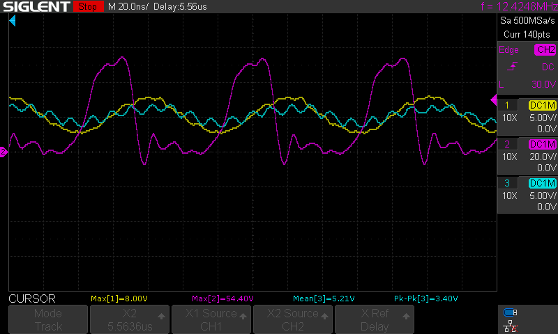
Hm. Clearly the device is overall functional but these waveforms aren't as clean as I'd prefer. Maybe it's fine?
All right, so let's walk through the component changes. I'll spare the step-by-step of each individual test -- most of it was poorly documented and I was going for more of a "better or worse?" approach than robust characterization.
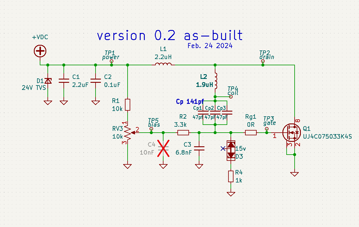
First off, primary tank capacitance was increased 99pF to 141pF. This was the first change made, as planned in previous project log "i would like my circuit to not cook myself".
Increasing capacitor value was broadly successful -- overall power draw was reduced to ~2.9 - 3.2A depending on circuit configuration. Yay!
Decoupling cap C4 was removed because it caused some kind of runaway oscillation on both gate voltage and power draw. A different cap value might be fine but for the moment, the pads are empty.
I spent quite a while trying to increase operating gate drive voltages. You can see in the second pic that gate drive peak is only 8V, when I'd have preferred something closer to 15. My understanding is that MOSFETS really prefer to be driven by a square wave rather than this sinusoidal feedback. With intermediate voltages near the switching threshold the mosfet is in a state of "kinda-on", which causes a lot more power loss (and thus heat) than being fully on or fully off.
I was hoping that larger values of R2 would strengthen gate drive and increase the differential between the gate voltage and the (still too wiggly for my taste) bias voltage. Initially I spec'd R2 for 10k in this iteration, but it turned out that overly large values resulted in too tenuous of a ground reference. The max stable value I tested was 3.3k for R2.
Similarly, decreasing gate capacitor C3 to 6.8nF increases gate drive voltage a bit, but it's not as dramatic a difference as I'd have expected.
Playing with the gate resistor Rg was a bit odd. Looking at the traces I saw very little change with values ranging from zero ohm to 10Ω. Subjectively, 0Ω seemed to cause the least heating of the mosfet, but I wasn't taking rigorous enough measurements to say that with certainty. (Also, the 10Ω resistor almost immediately toasted itself; the gate capacitance is slurping far more power than a little 1206 smd can handle.) I wasn't able to observe any kind of difference in probable turn-on delay based on scope measurements.
Looking back at the drain traces in the toroid-loaded condition, I see a couple of things:
- Drain voltage peaks at only 55-65V or so.
- Drain ringing after turn-on, including temporarily shooting negative.
I don't even know if either of those is even really a problem. I may investigate using a higher inductance feed coil L1 -- other folks describe 10uH, I'm only using 2.2k. Might also look into a schottky diode across the mosfet to clamp drain against going negative.
Returning to the topic of board thermals:
The key discovery was that heating on the inductor coil and the primary capacitor bank goes way
down when the xenon is actually ionized toroidal. I believe this lends some credence to the idea of framing coil heating in terms of "input energy has to go somewhere".
I also hooked up a little 40mm axial fan and aimed it at the board heatsink, and stuck a teeny copper heatsink on top of the mosfet.
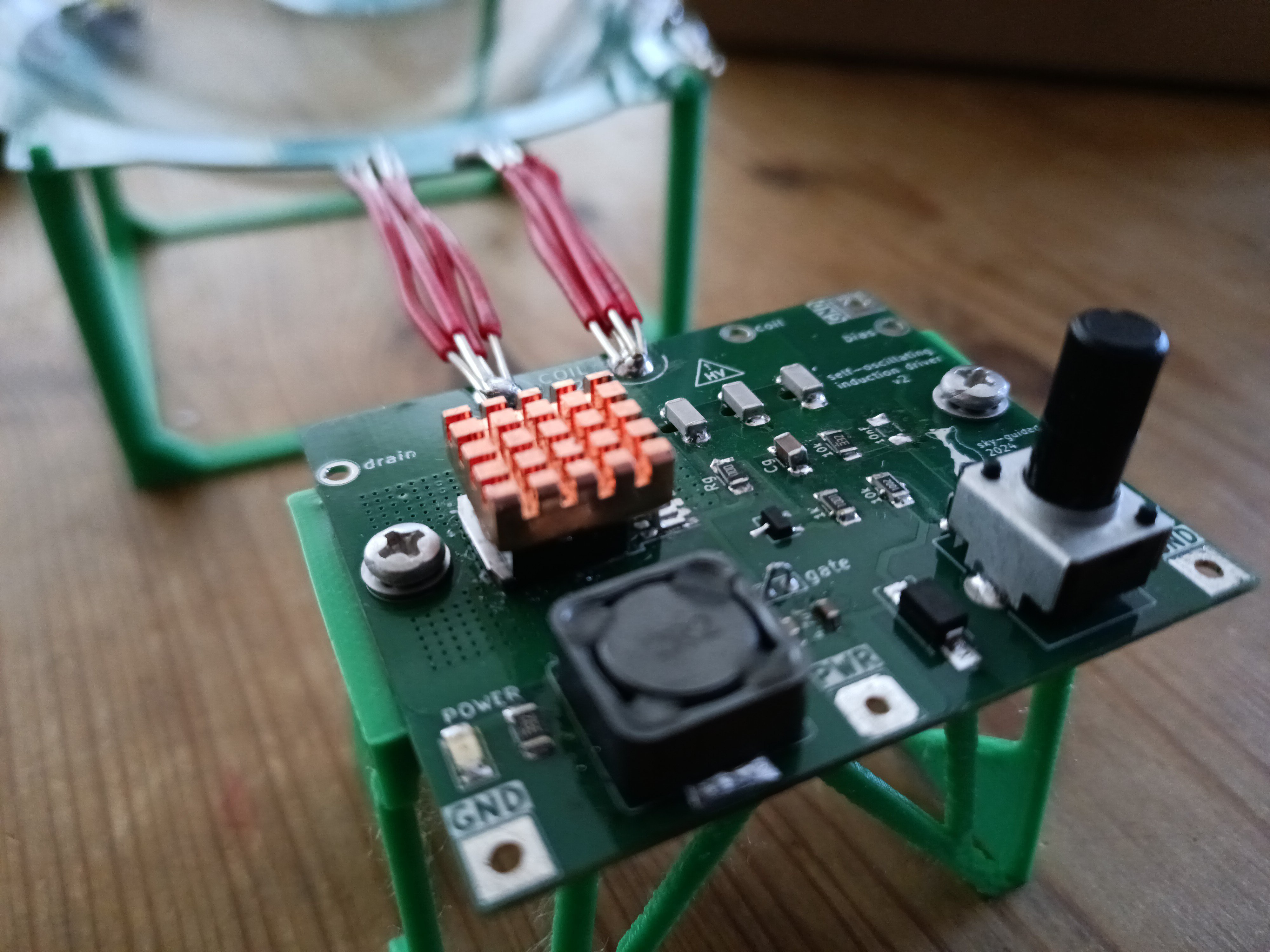 With all of the changes, I was able to get temperatures to stabilize at ~100-110C on the mosfet body and ~50-60C on the coil while the toroid was active.
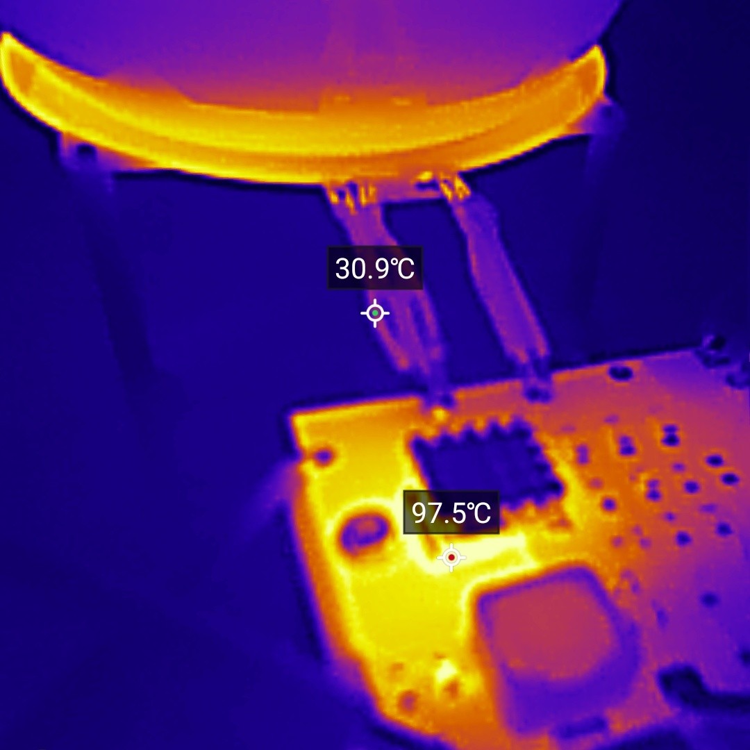 That's hotter than I'd like, but... basically fine. It means that at the moment I can run the device for minutes at a time without worrying about it bursting into flames. Still probably worthwhile to use coil with wider traces, use more capacitors in the primary bank to spread out the load a bit, try to reduce mosfet losses, etc. Again though, yay!
Stay tuned for more!
Discussions
Become a Hackaday.io Member
Create an account to leave a comment. Already have an account? Log In.