 sky-guided
The electromagnetic fields generated primary inductor aren't strong enough to ionize neutral xenon gas into plasma. Once any infinitesimal part of the gas is ionized, those charged particles almost instantaneously cascade into their neighbors and the whole globe lights up. But getting a bit of gas to ionize in the first place is the tricky part.
The "standard" way to do this (as demonstrated by BacMacSci) is to forcefully twist the glass globe against the induction coil. The triboelectric effect causes miniature "static electricity" shocks which are enough to kick off ionization. Alternately, one can use some kind of external high voltage source like a handheld tesla coil zappy gun.
Either manually twisting the globe or using an external device is a bit dissatisfying to me. I wanted to integrate arc start directly into the device, activated by the push of a button.
This log is going to be longer than most, because it's been an adventure.
An external zap?
My first attempts were using cheapo "arc lighter ignition modules" sold on aliexpress or amazon. (I won't bother linking, because those listings seem to have a half-life of like six months and dead links suck.)
zap
BigCliveDotCom has a great video explanation into how this circuit works. I think it could be best described as "aggressively cost-optimized.
Holding the contacts against the globe could occasionally start ionization, but that was rare. Most of the time it did nothing, regardless of positioning.
This was a dead end.
So I thought, well, xenon flash tubes for cameras and strobe lights and stuff exist. How do those work?
Triggering xenon flash lamps
BigCliveDotCom also has a video on how xenon flash lamps are fired, titled "Unwinding a tiny 6kV xenon trigger transformer". He's phenomenal at concise explanations of how circuits work and this is no exception -- I'm going to embed it here, because his description is better than what I can muster. The circuit diagram and explanation is from about 1:53 to 4:30
The shortest version is that a small capacitor is charged to the neighborhood of 300V, then rapidly discharged through the primary of a high-turns-ratio transformer. This creates a very high voltage pulse on the transformer secondary, which is fed to a fine wire wrapped around the glass of the xenon flash tube. The high voltage causes capacitive coupling to the xenon through the dielectric of the glass, strong enough for ionization.
Here's my implementation:
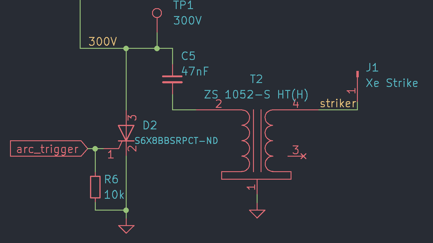
It's the same circuit BigClive drew. No magic here.
Component D2 is a thyristor, an old-school cousin of the BJT. When a voltage is applied at the gate it latches closed until current flow drops below a low threshold value.
Getting 300 volts
There's lots of ways to get 300-ish volts from low-voltage DC, and most of them are some variant of flyback converter.
Properly engineering a flyback converter is a bit of a rabbit-hole, and these days it seems like most commercial applications are in low-volt-dc switch-mode power supplies. I decided to take the shortcut of using the LT3420, an IC purpose-built for charging photoflash capacitors.
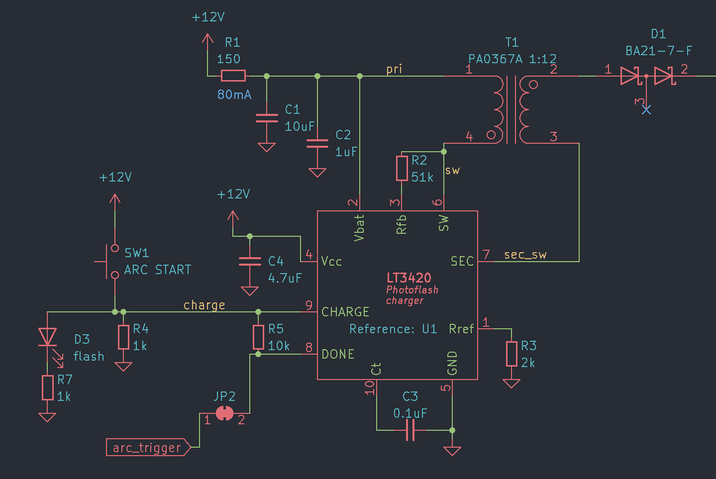
This is very nearly the same circuit as the reference design in the datasheet. I'm even using the same flyback transformer that they recommended. (That's one thing I love about hobby electronics -- device manufacturers actively do what they can to make implementation of their parts as easy as possible.)
There's a couple of deviations from reference, though. R1 is a current limiting resistor; since I'm only charging the teeny 47nF trigger capacitor and not a larger flashtube cap, I can store the needed energy in a "slow"-charged onboard 10uF cap rather than the transformer drawing directly from the 12V rail (and correspondingly needing a 12V regulator with a higher current rating).
The DONE pin goes high when the IC thinks that the transformer output has been charged to the nominal voltage. My design intent here was to use this signal to automatically fire the triggering thyristor when the threshold was reached. Normally DONE has a pullup, but I decided to get overly clever and pull it up to the CHARGE line so that in theory it could only go high when the arc start button is pressed.
JP2 is a cuttable jumper trace, since I figured that I might have issues with thyristor trigger reliability and need to try external trigger signals. This ended up being a prudent bit of defensive design.
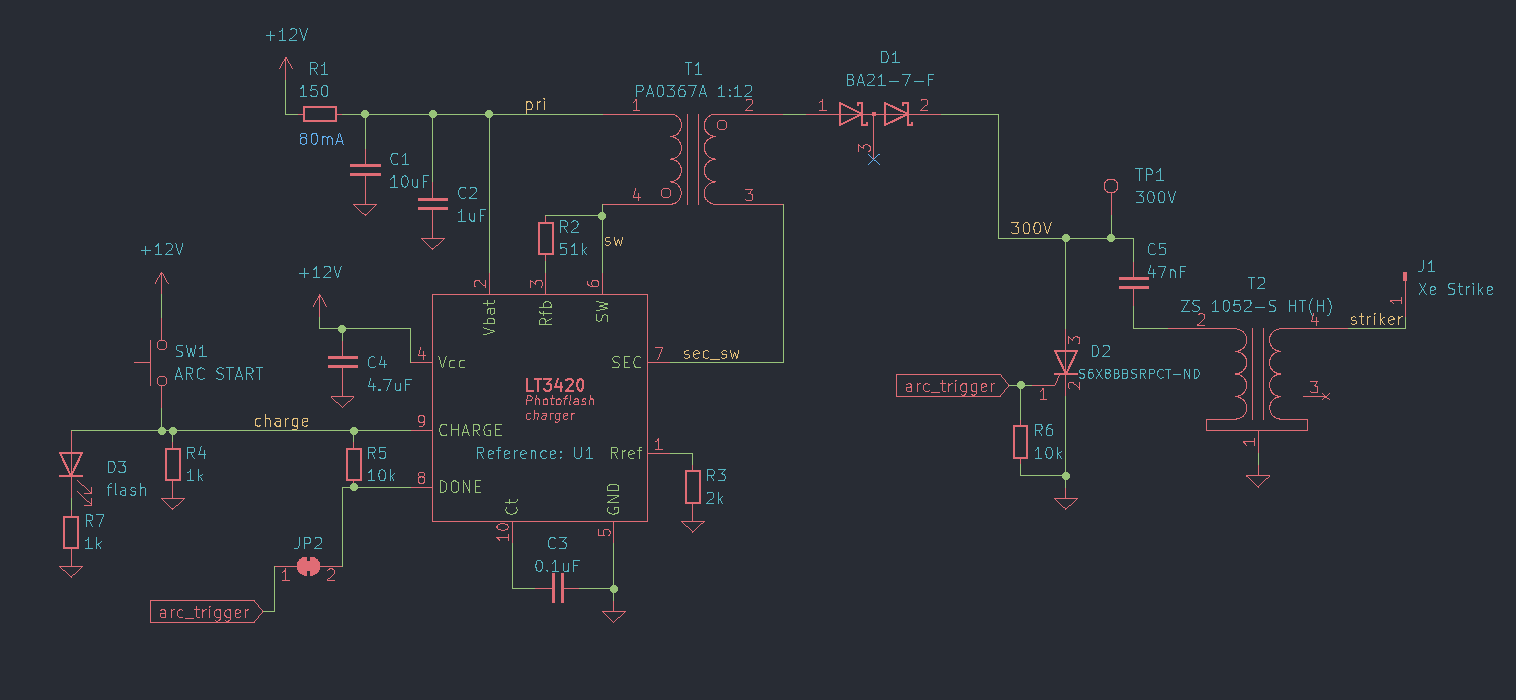
Putting the 300V charger and the trigger circuit together, here's what we get:
A downside to this approach is parts availability and cost. Xenon flashtubes for photos have fallen out of favor so these have become "specialty components". In particular, the LT3420 costs like $8 each, and the transformers together are about $7. That might not seem like much but it adds up when buying prototyping quantities of even just five or ten pieces.
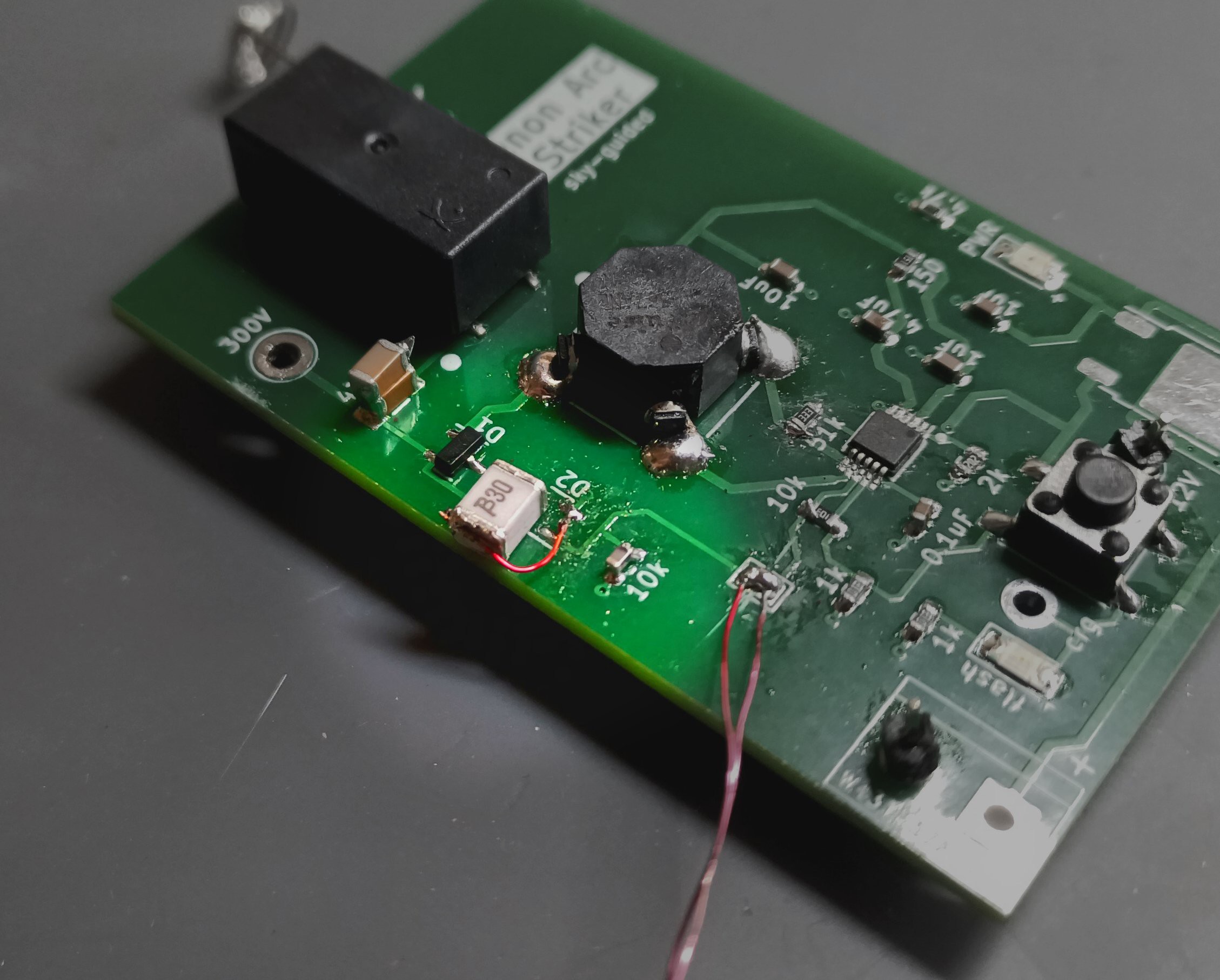
Circuitboard
As previously, this board was sponsored by PCBWay! Their product quality is, as always, solid.
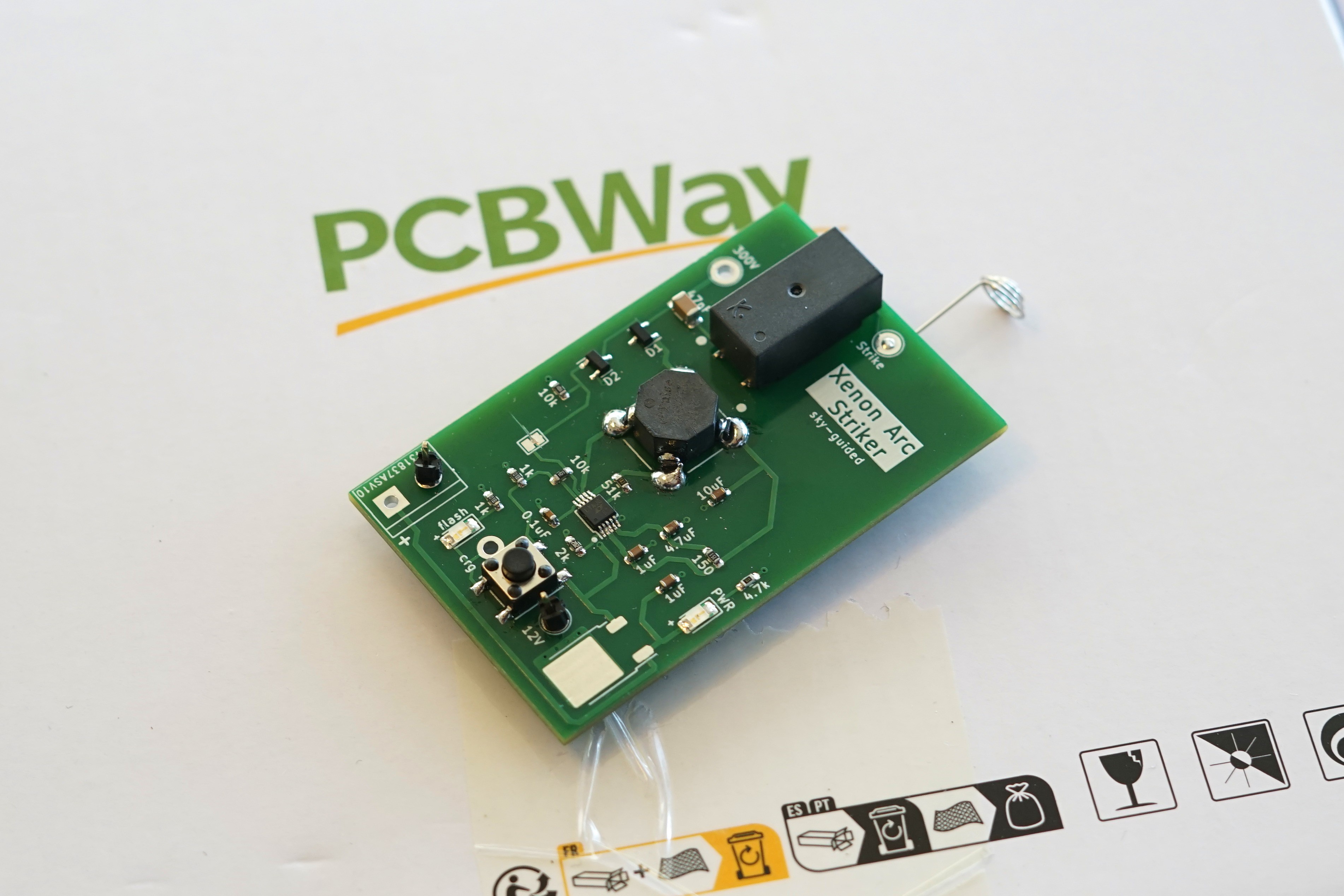
The actual contact point for the xenon globe is a little spring-steel AAA battery terminal, extending to the upper-right. A little bit of of hand forming is required, but the springy contact is great for gently conforming to the globe's surface. A wire wrapped around a cylindrical flashtube may be traditional, but trying to wrap around a spherical glass vessel is misery.
Unfortunately, I made no less than four different errors when laying out this board:
- There was supposed to be a 12V regulator on board, but it's unpopulated (the large footprint at the board's bottom). This was because I made a last-minute decision to swap the regulator I had on order from one with a DPAK footprint to a smaller SOT89, and I neglected to update the layout.
- The Pin 1 marker on the (octagonal) flyback transformer is on the wrong side -- I had primary and secondary backwards. Probably a mistake in the "alternate pin assignments" options in KiCAD.
- The footprint of the flyback transformer is also wrong -- the spacing is too wide. I suspect when laying out the footprint I was entering pad edge-to-edge dimensions as if they were center-to-center.
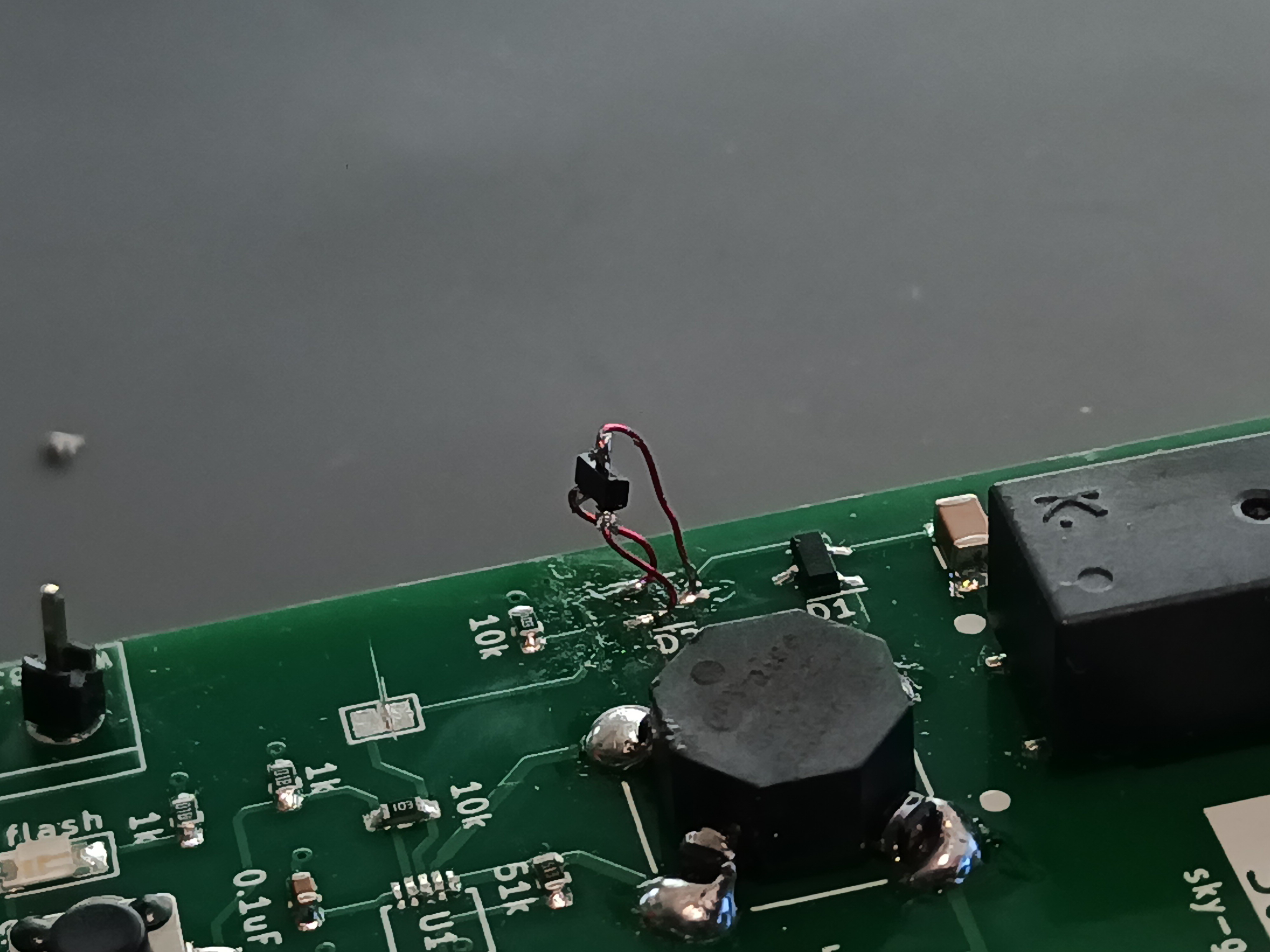
- The thyristor (D2) had gate and cathode pins swapped. This last was fixable with a bit of bodge wire excellence:
With the board assembled and the bodges all bodged, did it work?
Well... kinda.
First iteration: almost working, but not quite
The flyback was successfully able to charge the trigger cap up to >300V. Quite a bit higher, in fact -- the voltage was going literally off the scale that my scope would display. The charge control IC should have automatically ceased charging when the output hit a voltage threshold programmed by a feedback resistor, but in practice I think it was charging the 47nF trigger cap fast enough that the IC control got kinda wibbly -- in a usual application it'd have caps which would charge on the order of several seconds, not a few milliseconds.
With full charge, I could manually short the high side of the trigger cap to ground, and produce the sharp-edged pulse to drive the trigger coil. Doing this could sometimes cause the xenon globe to ionize, but it was very inconsistent.
Getting the thyristor to switch consistently was a minor ordeal. First there was the aforementioned "gate and cathode were wired backwards" problem. Then there was a bit of a wild goose chase seeing if an external 555 timer circuit could produce more reliable results than the DONE signal from the IC. Eventually I determined that the thryistor could switch just fine when the board was sitting on the bench, but when I tried to actually use it to strike the toroid arc, the driver's primary inductor was causing electromagnetic interference so intense that the thyristor was firing prematurely. Replacing the 10kΩ pulldown resistor with a 1nF bypass capacitor helped a bit, but it was still never able to get the xenon to ionize.
Second iteration
I had to take a step back and ask myself, "what problem am I actually trying to solve here?" The goal was to discharge the capacitor in a sharp pulse when it reached 300-ish volts. A DIAC could do this, but that would be yet another specialty component with terrible selection and availability. Alternately someone named Pagurja has a youtube video titled "The simplest xenon flash circuit" which demonstrates forcing a BJT into avalanche breakdown to create the fast pulse required. This is apparently a secret-sauce way of creating ultra-fast pulses for things like oscilloscope bandwidth characterization, but I wasn't excited by the idea of relying on semiconductors pushed so far outside of their designed and characterised regimes.
The breakthrough came when I saw this note from Lewis Loflin at bristolwatch.com describing using two ne-2 neon bulbs as part of a trigger circuit.
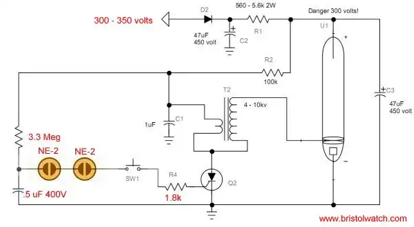
I figured, heck, why not use some kind of spark gap type thing as the trigger switch itself?
Web searching things like "specific voltage spark gap" etc lead to my discovery of a device called a gas discharge tube arrestors. These little guys are perfect -- it's a sealed tube with some magical gas mix inside, specifically designed to break down and conduct at a particular voltage. GDTs are generally used for circuit protection; they sit at near-infinite resistance unless a high-voltage transient comes down the line, at which point they function as an overvoltage crowbar. They even come in tiny surface-mount packages, at prices of well under a dollar.
I should give specific credit to this 2021 post on the EEVBlog forum from a user named Gyro. They link to a PDF copy electronics hobbyist magazine from way back in 1978, presenting a circuit that's conceptually nearly identical to what I need!
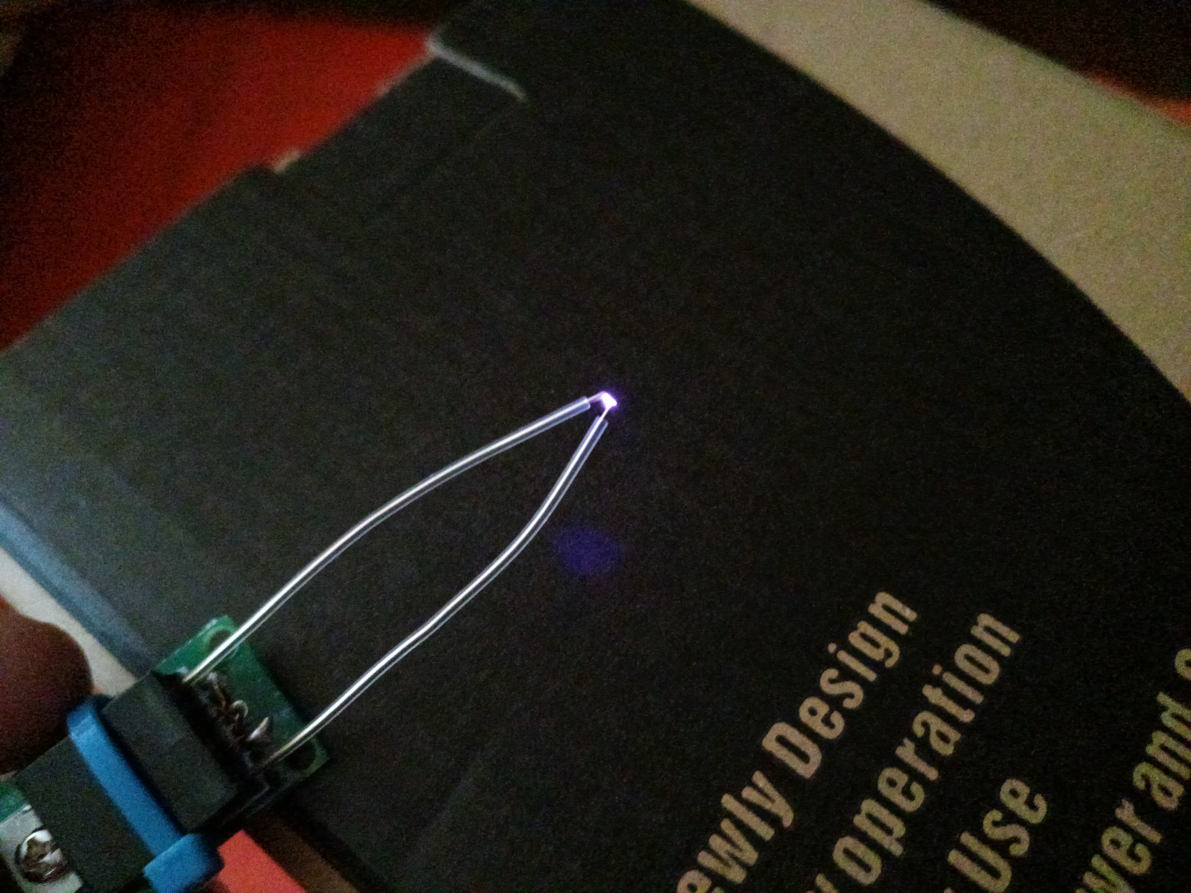
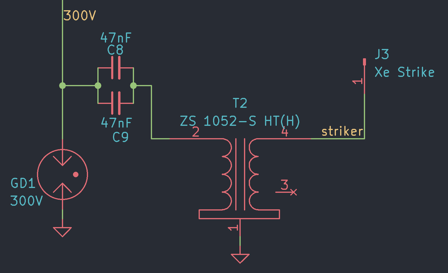
Here's what the revised trigger section looks like:
And here's the actual GDT, bodged in to the board in place of the thyristor. It's only a 1812-sized SMD part!
I double-stacked two of the 47nF capacitors during earlier testing, and didn't feel any strong need to change back to a single cap.
Results
Here's the scope waveform measured at the "300V" test point.
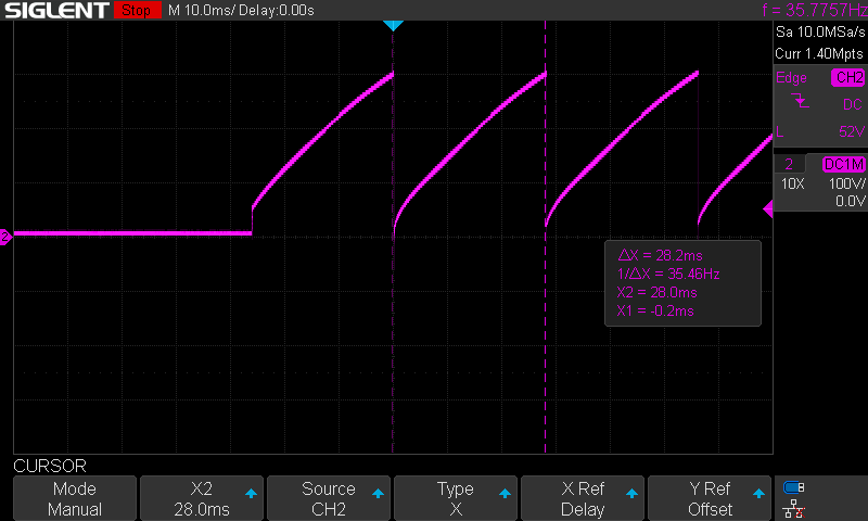
Exactly as intended. The capacitor is charged up by the flyback, then automatically discharges through the GDT when it hits 300 volts. Not pictured here is the corresponding high voltage pulse on the trigger transformer secondary. This happens at a frequency of 35Hz, so you get that nice clicky-buzzy noise reminiscent of a stun gun arc, but much quieter.
Zooming the timescale wayyyyyy in, here's a single discharge:
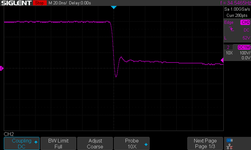
The pulse time is under 5ns. Not gonna set any records, but pretty quick.
Video demonstration:
As you can see, from a cold turn-on it takes a few bursts of the zappy to get going -- the xenon seems a bit harder to ionize before it warms up. Once the globe is warm, the module can strike an arc almost instantly.
In the final build this module will be integrated as part of the single driver PCB.
WHAT'S NEXT
Getting the arc start module working is a big deal. All of the individual subsystems are functional and core design milestones have been hit:
- Initially achieving the plasma toroid effect.
- Refining the driver to run continuously without melting.
- Tuning a plasma donut that can be either eerily stable, or intriguingly mobile.
- Powering the driver via USB-C (which I haven't yet described, since I'm using an off-the-shelf USB-PD board which Just Works in a delightfully boring way.)
- An indicator light for whether the circuit is in oscillation.
- Pushbutton arc start.
Now I gotta put all the pieces together. I'm certain the result is going to be gorgeous.
See you next time!
Discussions
Become a Hackaday.io Member
Create an account to leave a comment. Already have an account? Log In.