 kutluhan_aktar
Nevertheless, there are still a few grand challenges to overcome while applying mechanical anomaly detection to mass production operations, such as the scarcity of data sources leading to false positives (or negatives) and time-consuming (or computationally expensive) machine learning methods[3]. Since every manufacturing system setup produces conflicting mechanical deviations, the optimal anomaly detection method should be deliberately specialized for the targeted setup, which minimizes false negatives and maintains exceptional precision. If the mechanical anomaly detection method is applied without proper tuning for interconnected manufacturing processes, the applied method cannot pinpoint the potential root cause of the detected mechanical anomaly. In that regard, inefficient anomaly detection methods still require operators to conduct manual inspections to diagnose the crux of the system failure.
After inspecting recent research papers on autonomous anomalous behavior detection, I noticed that there are very few appliances focusing on detecting mechanical deviations and diagnosing the root cause of the detected anomaly so as to provide operators with precise maintenance analysis to expedite the overhaul process. Therefore, I decided to develop a device to detect mechanical anomalies based on sound (via an onboard microphone), diagnose the root cause of the detected deviation via object detection, and then inform the user of the diagnosed root cause via SMS.
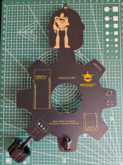
To be able to detect mechanical anomalies and diagnose the root cause efficiently, I decided to build two different neural network models — audio classification and image classification — and run them on separate development boards to avoid memory allocation issues, latency, and reduced model accuracy due to multi-sensor conflict.
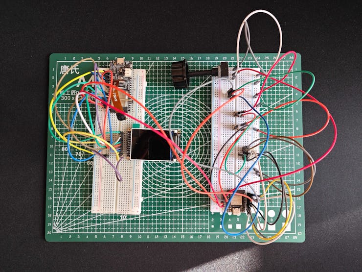
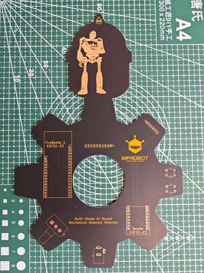
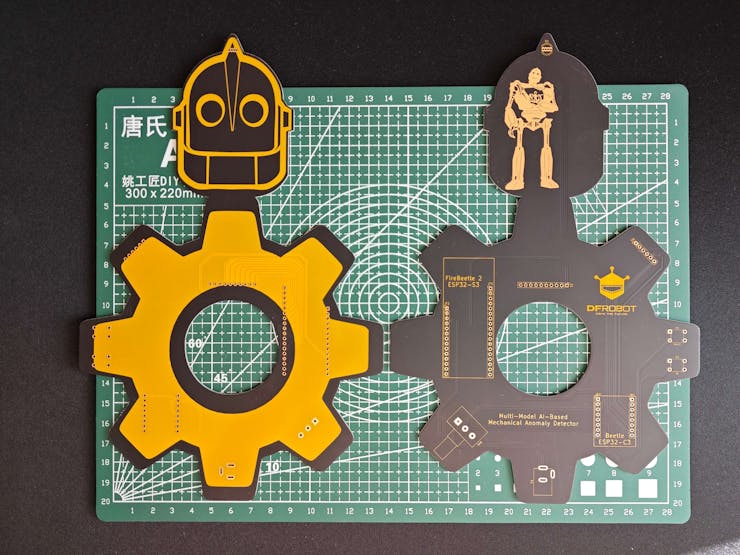
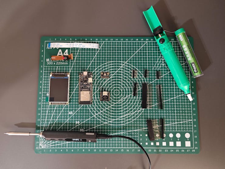
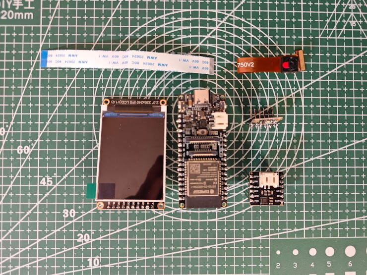
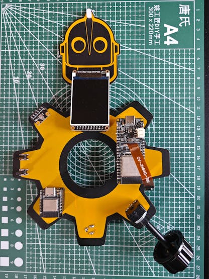
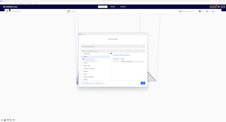
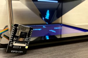
Since FireBeetle 2 ESP32-S3 is a high-performance and budget-friendly IoT development board providing a built-in OV2640 camera, 16MB Flash, and 8MB PSRAM, I decided to utilize FireBeetle 2 ESP32-S3 to run the object detection model. To run the neural network model for audio classification, I decided to utilize Beetle ESP32-C3, which is an ultra-small-sized IoT development board based on a RISC-V single-core processor. Then, I connected a Fermion 2.0'' IPS TFT display to FireBeetle 2 ESP32-S3 in order to benefit from its built-in microSD card module while saving image samples and notify the user of the device status by showing feature-associated icons. To perform on-device audio classification, I connected a Fermion I2S MEMS microphone to Beetle ESP32-C3.
Even though this mechanical anomaly detector is composed of two separate development boards, I focused on enabling the user to access all interconnected device features (mostly via serial communication) within a single interface and get notified of the root cause predicted by two different neural network models — sound-based and image-based. Since I wanted to capitalize on smartphone features (e.g., Wi-Fi, BLE, microphone) to build a capable mechanical anomaly detector, I decided to develop an Android application from scratch with the MIT APP Inventor. As the user interface of the anomaly detector, the Android application can utilize the Wi-Fi network connection to obtain object detection model results with the resulting images from a web application, save audio samples via the built-in phone microphone, and communicate with Beetle ESP32-C3 over BLE so as to get audio-based model detection results and transmit commands for image sample collection.
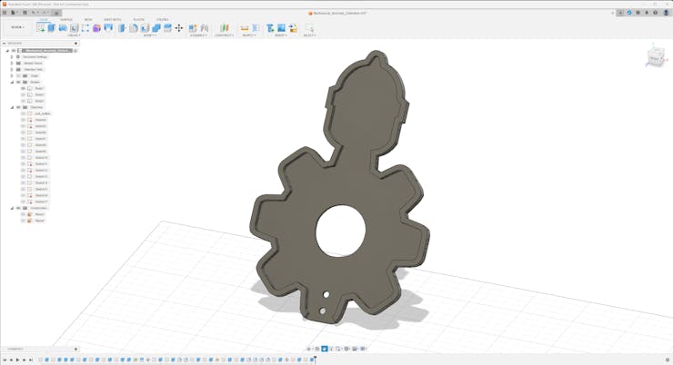
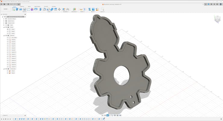
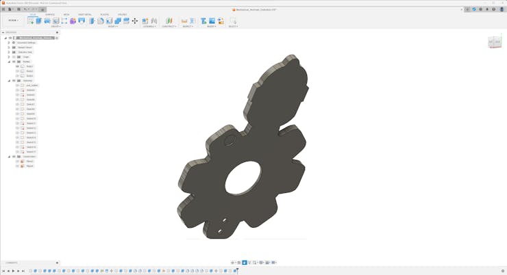
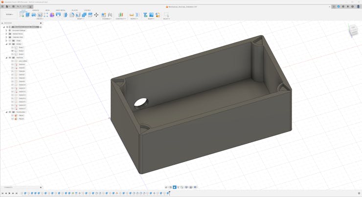
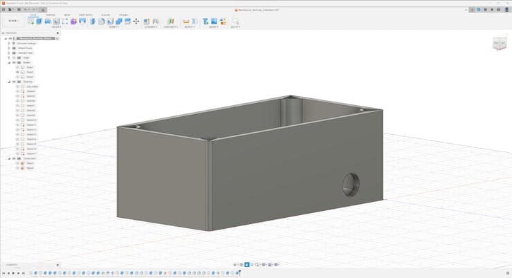
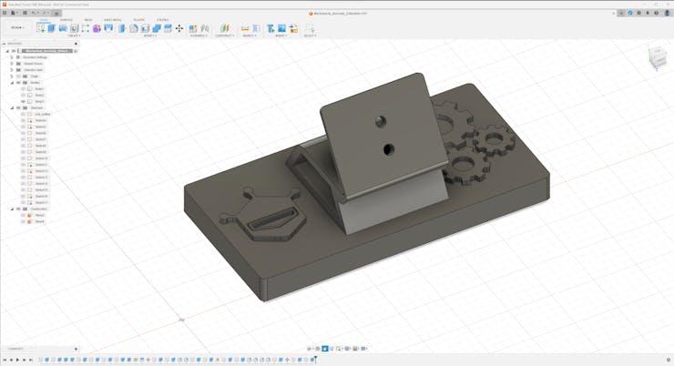
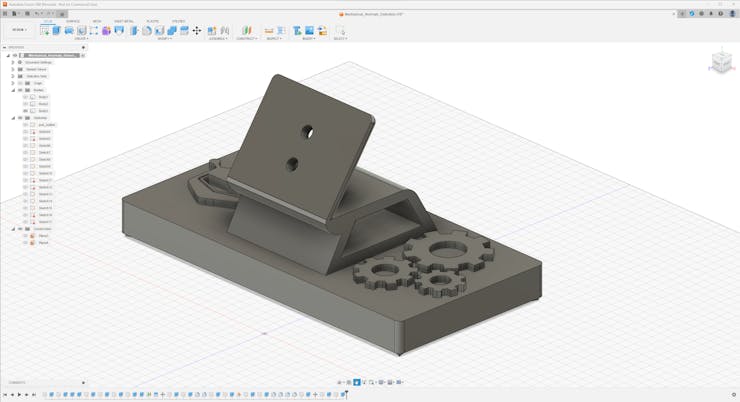
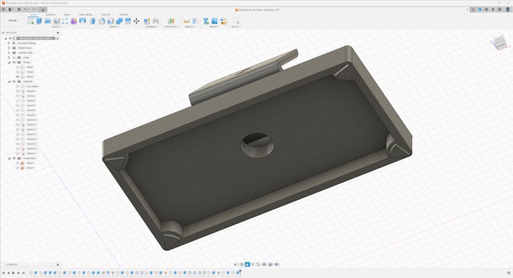
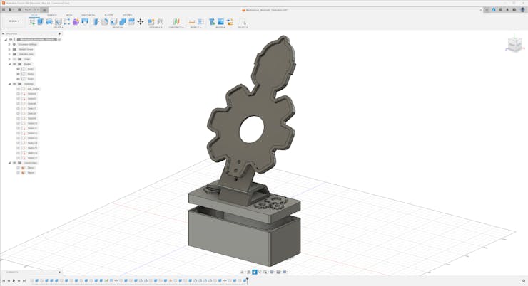
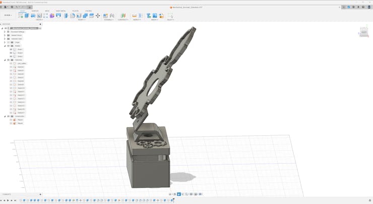
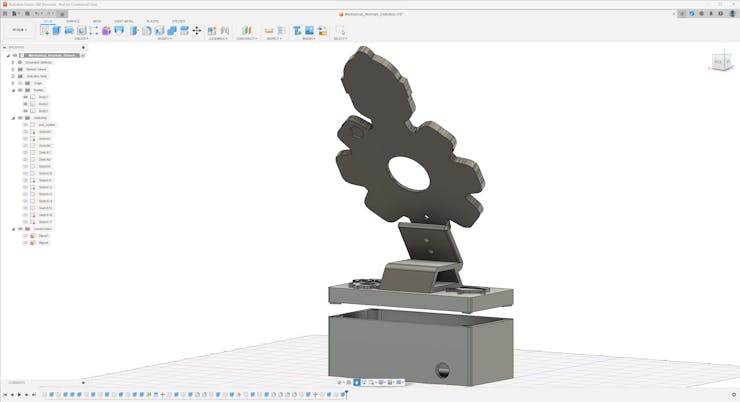
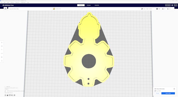
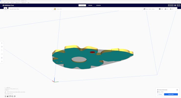
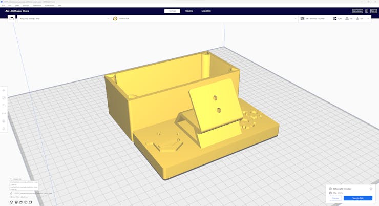
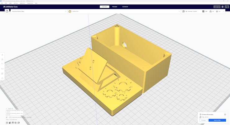
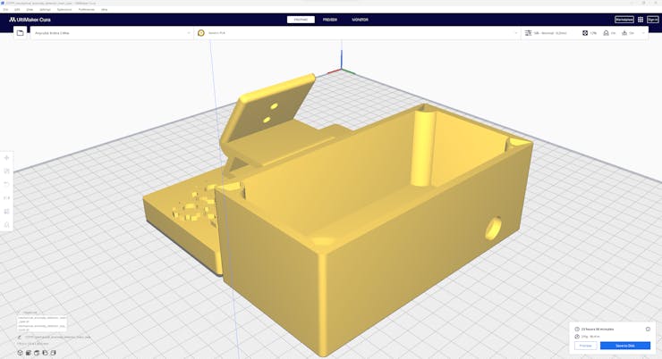
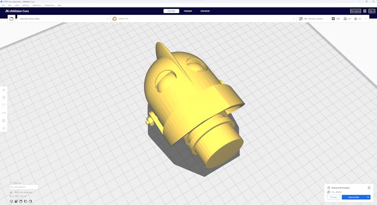
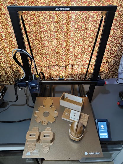
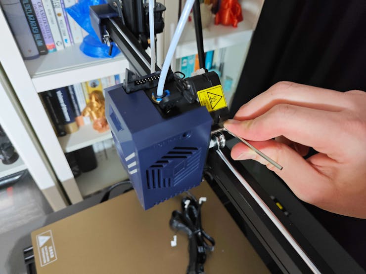
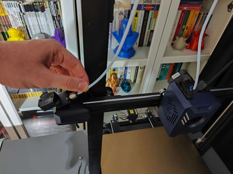
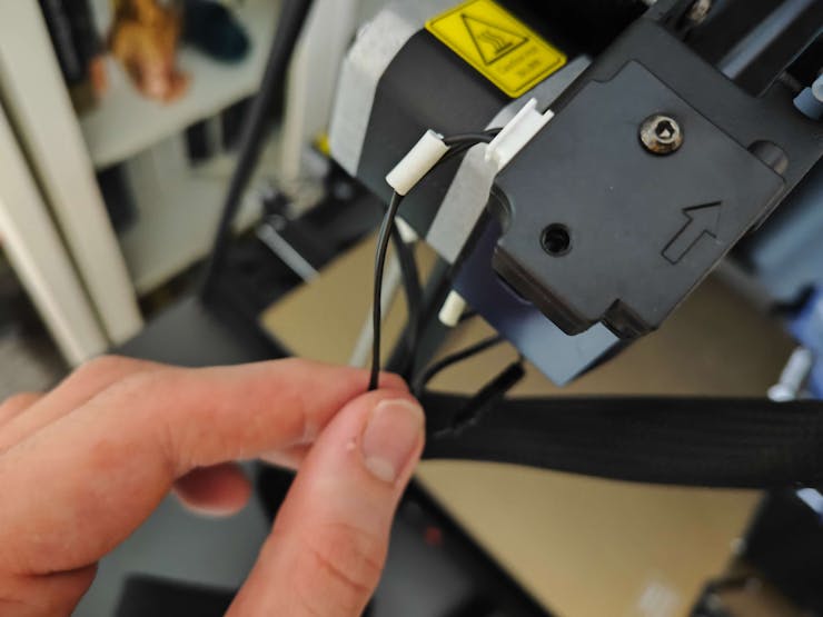
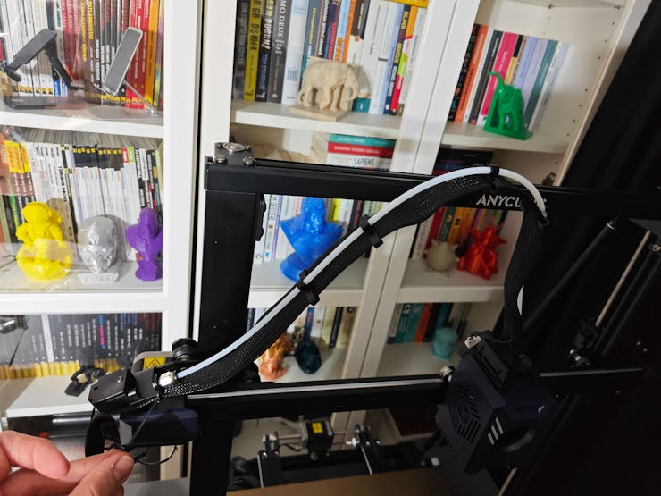
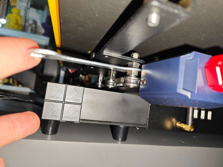
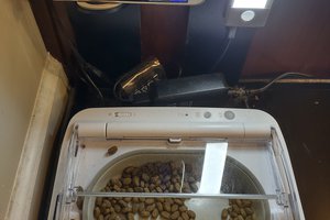
As explained earlier, each manufacturing setup requires a unique approach to mechanical anomaly detection, especially for interconnected processes. Hence, I decided to build a basic frequency-controlled apparatus based on Arduino Mega to replicate mechanical anomalous behavior. I designed 3D parts to contain servo motors to move a timing belt system consisting of a GT2 60T pulley, a GT2 20T pulley, and a 6 mm belt. Since I utilized potentiometers...
Read more »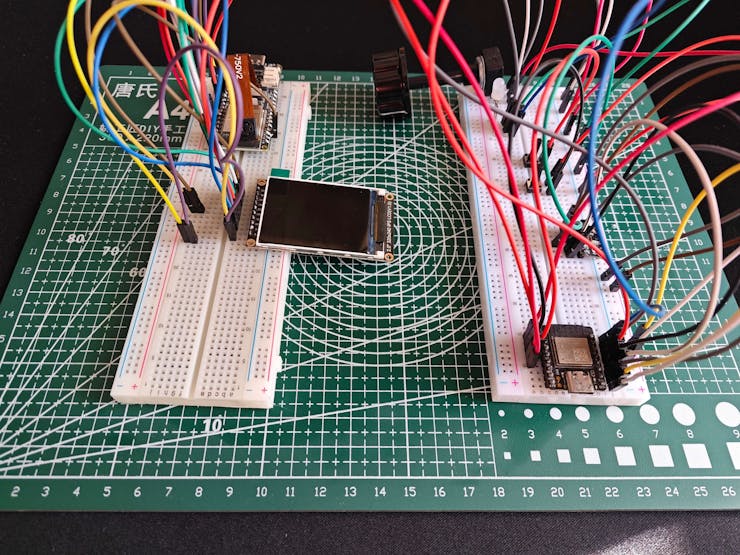

 Yi-Wei Chen
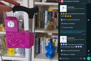
Please feel free to leave a comment here if you have any questions or concerns regarding this project 😃