 TheBrokenEngineer
While I am waiting for the boards to arrive, the time could be spent explaining the idea behind a separate programmer/debug board.
As mentioned in a previous post, there is no way of programming the microcontroller while it is installed on the thermometer board. The reason for this choice is to make the layout simple and the fact that the programming header would not be used all that frequently. The downside is that there is no way of programming the microcontroller rendering the device useless.
This is where the separate programmer/debugger board comes in. Depending on the components fitted it can be a programmer, programmer/debugger, or both.
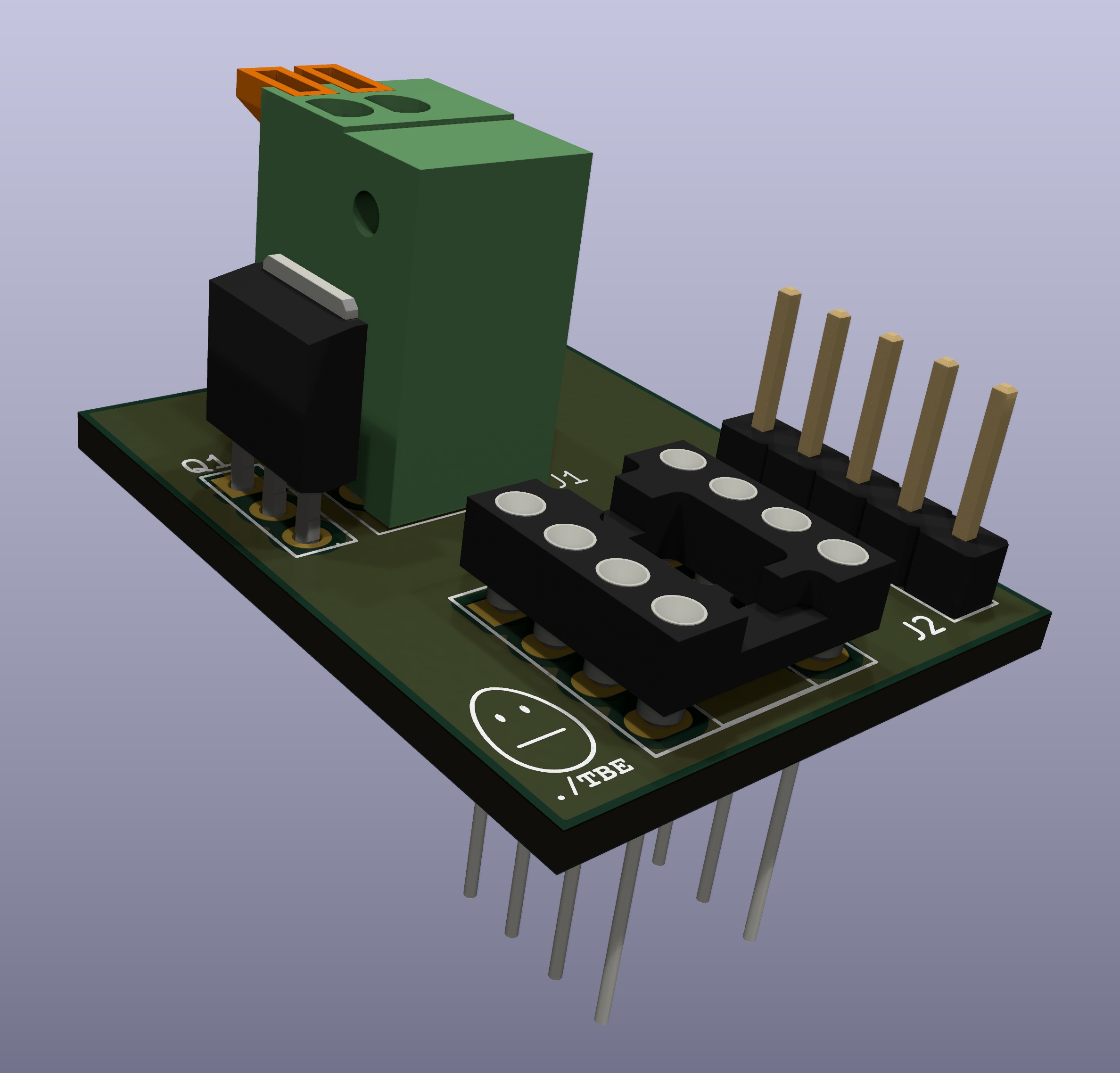
Starting with the programmer, the board is fitted with a 5-pin header, standard DIP-8 socket and two wire spring terminals for power. The microcontroller to be programmed is inserted into the socket, 5-volt DC power is supplied via the spring terminal connectors and the PICkit-4 programmer plugged into the header. The chip is then programmed using the MPLAB X IDE. An additional feature is the reverse voltage protection for the power input terminals which is implemented using a p-channel MOSFET. In this configuration ALL components in the schematic must be fitted.
The second configuration is as an in-circuit programmer/debugger. This required the fitting of a wire wrap DIP 8 socket and 5-pin header. All other components can be omitted as the power supply for the microcontroller is provided by the desktop thermometer. The board is then plugged directly into the socket on the thermometer board and the thermometer is powered up. Once the PICkit-4 is attached debugging and programming can be performed using the IDE.
The final configuration is to populate the board with all components like that of the programmer configuration replacing the standard DIP socket with the wire wrap socket. This allows for the power to be connected to the board and used as just a programmer. Additionally, the board can be plugged into the target thermometer device with the programmer board connected to a 5-volt supply. The advantage is the programmer powers the desktop thermometer removing the need to plug the thermometer into a USB power supply.
This all might be a little hard to visualize so the non-AI rendered (KiCad viewer to the rescue on this one) image below might help.
Discussions
Become a Hackaday.io Member
Create an account to leave a comment. Already have an account? Log In.