CanHobby.ca
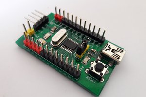
I recently acquired a WeAct Studios ESP32-C3 Risc-V Arduino development board. I found it different enough your your "standard" devKit I thought I would share my finding in the hope it might be useful to someone out there. At first glance it looks very straightforward but the ESP32-C3 has a few tricks up it's sleeve. The board was very inexpensive ( < $CAN 5) and achieves this by leveraging some of the built-in features of the "C3". So here is the story. My objective was to get the "Blink" sketch going, as well as, messages from the Serial port(s).
The board comes with a single USB-C connector so one would typically connect it to your USB and try to upload the Blink sketch having selected ESP32-C3 Dev Module as the board. I normally prefer to the the "Generic" board rather then hunt down a vendor specific board which may or not be correct, or even exist. Of course, one must be aware of the limitation of the actual board being used.
So I added/updated the latest ESP32 boards package from Espressif (note the Arduino package is often 1 or 2 revs behind the latest Espressif stable release) which can be found here. The latest ESP32 package includes all of the EDP32 series including the 'C' RISC-V series.
Here is a copy of the sketch I used:
#define LED_BUILTIN 8

void setup() {
  pinMode(LED_BUILTIN, OUTPUT);
  Serial.begin( 115200 ); delay( 100 );
//  Serial0.begin( 115200 ); // delay( 100 );
  Serial.println( "\nSetup: This is Serial\n" );
//  Serial0.printf( "\nSerial0 says LED is on %d\n\n", LED_BUILTIN );
}

void loop() {
  Serial.println( "Loop: This is Serial" );
//  Serial0.println( "Loop: Serial0 reporting" );
  digitalWrite(LED_BUILTIN, HIGH);   // turn the LED on (HIGH is the voltage level)
  delay( 1000 );                     // wait for a second
  digitalWrite(LED_BUILTIN, LOW);    // turn the LED off by making the voltage LOW
  delay( 1000 );                     // wait for a second
}
I connected the board to my computer via USB and looked under "Port" in the Tools menu. AND found nothing. The LED on the board was flashing as if it had a Blink sketch pre-installed. Looking at the board I did no see a USB to UART chip, so, being somewhat familiar with recent Espressif MCUs with integrated USB peripheral(s), I tried to enable the CDC serial port. To do this you hold down the "BOOT" button, then press and release the "EN/RST" button, and then release the "BOOT" button. This produced a /dev/ttyACM0 (would be different on Windows) port in the list. (It should be noted that the port declares itself as an ESP32S3 Dev Module) - most likely a programming oversight on WeAct's part. The Port Name is programmable from a Sketch.
So I hit the Upload button on the IDE and was rewarded with the usual output of a sketch upload... BUT, no out put on the serial monitor, neither was the LED blinking... I went back to the AliExpress listing where I bought the board and although it provided little info they did indicate that the LED was on GPIO 8. I added the "#define LED_BUILTIN 8" line at the top of my sketch, uploaded, and voila - the LED was blinking... but no serial output.
So... I connected the GND and RX pin of an external USB to UART module ( such as a CP2102 or FTDI ) to the GND and TX pin on the ESP32-C3 board. I then used putty to connect to the CP2102 and received the Serial output requested in the Serial.println() statements.
Seems redundant to have 2 serial ports in use - 1 for upload and the other for debug... Sooo... taking a page from my experience with the S3 I enabled the "USB CDC on Boot" option in the Tools menu. I also uncommented the Serial0.... statements... AND... was rewarded with the "This is Serial" messages repeating in the Serial Monitor, in time with the LED blink. BUT not the message from Setup(). Harking back to more ancient sketches I tried putting in a delay( 100 ) after the Serial.begin statement and the Setup...
Read more »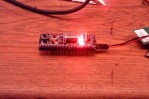
 Ethan Durrant
 Stefan Wagner
 jay-t
jay-t