 MS-Dzo
In the general description of the project, I briefly mentioned the 4 core units of the project :
- a general use input module to be able to get analog data in
- a general use output module to be able to get analog data out
- an HID module to interact with the system
- the Mixing module to actually work on the data
Those are obviously incredible simplified. In the next few logs i will write a bit about the inner workings of and limitations of each module, the protocols that will probably be used and why they'll be used.
This one will be dedicated to the star of the show, the MIXING MODULE
What does the mixer actually do ?
The mixer is able to take digitalized audio streams, process independently and together, then output them to the outputs selected. Here are all the features that i want
| Feature | Use Case |
| Stereo Sound through USB | Using Headphones or 2.1 systems |
| Modularity | You want to plug 2 PC and 1 guitar or 5 microphones and 1 PC |
| Per Output Input selection | You want Output 1 with Input 1, Output 2 with Input 1 and 2 |
| Per Input volume control | Allow to turn down your microphone if it's too loud |
| Per Output volume control | Allow to turn down music if it's too loud |
| Each Input get its own EQ / filter | If your microphone is hissing, you can remove it from all the outputs easily |
| Each Output gets its own EQ / filter | Make using a subwoofer or a tweeter at high power easier |
| Each Output gets its own delay line | Allows to synchronize all outputs, if one is too delayed because of filtering |
Specs aren't the point of this project, i want them to be lax enough to have fun and to learn : I'm not looking for a 0.0001% THD or something like that, at least not for now.
My setup is rack mounted, so it'd be fun if the modules were rack mounted too / something akin to eurorack in a 19 server rack ? ¯\_(ツ)_/¯
What Audio Streams format are we choosing, and why ?
the audio streams will be encoded in PCM over I2S because it's a standard and makes creating input and output modules easier since compatible ICs already exist.
NB : every stream from now on is considered stereo, until specified otherwise
In simple terms, PCM means that the audio signal is encoded by saving its amplitude at a specific frequency. a 8bit 1kHz PCM stream means that every milisecond, you get a byte of data representing the amplitude of the audio signal. 0xFF is the maximum (positive values) , 0x00 is the minimum (negative value) and 0x0F is the middle point or zero.
NB : those values are not representative of volts or whatever, they're normalized. each ADC has a gain of "bits per volt" called resolution that ISN'T shared to the system. this means that over the entire processing chain, we have no clue how loud the sound is. This tie with issues like headroom, clipping etc.
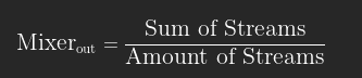
The fact that we are encoding amplitude makes mixing absurdly simple :
NB : this result only works if all the streams are at the same frequency
The mixer must be able to be used for recording music, so instead of the average 48kHz sampling frequency, we will go with 96kHz. This roughly means that if you want to process your instrument by slowing it down by a factor of 2, you will still end up with a 48kHz sampling frequency. This doesn't increase quality in any other way.
N.B : Some acquisition cards go up to 384kHz for the same reasons, we could but we won't go near that since i have no way to actually test it nor do i care about it.
With the same idea, we'll go into audiophile territory a bit and go with 24bit encoding instead of 16bit, even though the differences can't be heard. Following the same logic as choosing 96kHz over 48kHz, this will allow more flexibility when processing amplitude instead of frequency (ie : you can digitally amplify audio more before hearing distortions)
So, instead of going with the usual 16bit 48kHz, the inputs are 24bit 96kHz streams, which isn't that special for high end audio hardware.
Overflowing Issues and solutions
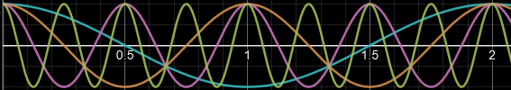
Let's say i have 4 inputs streams on 4bit playing a very loud cos wave, so loud in fact that at peaks the streams are at 0xF
Let's also say those cosinus waves play a frequency f, 2f , 4f and 8f respectively.
It just so happen that at t = 2/f you get all the peaks at the same time
If you add the signals at t = 2/f you get the following (in binary)
NB : if you add four 24bit streams you still get an overflow of 2 !
I hear you say " But you're not doing the Division by 4 which would solve the overflow problem !". Yes, it's true :
The prospect of adding 4 inputs (or 8) is quite attractive to us because division by a power of 2 is just a bit-shift. bit-shifting is x2 or /2 depending on the direction. However, our system has to work for all possible amount of inputs (1 2 3 4 etc.) so we have to do the division ourselves. and if you have 3 inputs, that division doesn't remove the overflow.
How do we deal with that ? there's three way and they all have their issue.
1 - Not dealing with the overflow and loosing information
If your input is 4bit and you want 4 inputs, just output 4 bits. that's it.
Just bitshift back to 4 bit, you'll loose the least significant bits of data. over 4 bit that's quite the issue but over 24 bits and depending on the quality of your audio system i bet those bits are basically noise to your ears. still, it's not an ideal solution
2 - Not dealing with the overflow and loosing money
If your input is 4bit and you want 4 inputs, just output 6 bits. that's it.
In our case, we could normalize our outputs to be 32 bits 96kHz (it's another standard) which works out nicely. However with no post-processing your sound is suddenly 2^(32-24) = 256 times quieter. that's a whopping -48dB reduction.
Since you know your number of input you can bitshift (multiply by 2^n) the correct amount of time to deal with that sound reduction. You don't loose information that way, but you do pay a price : you now have to transfer 32 bits back instead of 24. so the DACs and USB bridges must be able to deal with 32 bits.
3 - Dealing with the overflow with math
The arctan function basically starts linear and slowly goes toward a specific value. by transforming it a bit we can achieve something like this :
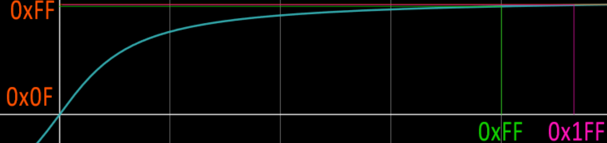
As you can see, for low values, x=y so the input and outputs are the same, but as the inputs tend toward infinity (or rather, as the input get overflown) the value tend toward the maximum allowed, 0xFF.
This works wonderfully, is SUPER cheap to implement (you just need a LUT ) buuuut it adds distortion.
I think i'll pass on this one, but i'm not sure yet !
EQ, Filters ?
I won't go into details, since i haven't done the math yet on what's achievable on a reasonably priced FPGA. I have experience as a student from using Artix 7 dev boards but at 150€ per chip, i'm not too keen on using those (although they are 100MHz beasts, they're way too overkill)
The idea however is just to add simple superposed digital band stop filters to act as the EQ.
Delay line ?
I won't go into details, since i don't have the appropriate hardware to implement it.
The idea is that the previous filters will offset the signals in the time domain : they'll come late by a factor of its frequency. this cannot be avoided, and it means that the smaller the frequency the bigger the offset in the time domain, which can end up in the 20s of ms.
One solution is to add a Delay line per output, and use them to add delay to every output so that they're all synchronised with the slowest output :
- Output 1 is 1 ms late
- Output 2 is 10 ms late
- You add 9 ms of delay to Output 1
- both Outputs are 10ms late and synchronised. Yay !!
The easiest way to implement this is with RAM and using a circular buffer, which our FPGA can easily handle.
USB ?
Ah. Here comes trouble. Turns out that USB is super high speed and need dedicated hardware, a run of the mill FPGA won't be able to implement with it. Also turns out that USB to I2S and I2S to USB *isn't* a standardized thing. our 24 bit 96kHz input 32bit 96kHz output don't have dedicated ICs. Also, There's no way to use other things than PCM (DSD is a big thing in the audiofools community, but it'd be fun to implement too. maybe)
The general solution if you look up for this online is to just make it yourself. so guess what we're gonna do ?
That's right, we're gonna take an STM32 or whatever and write a duplex bridge : USB to I2S and I2S to USB.
We'll see this later.
Discussions
Become a Hackaday.io Member
Create an account to leave a comment. Already have an account? Log In.