 MS-Dzo
What is it ?
The Input module doesn't technically needs to exist for a purely digital system, but as I plan to use this with analog devices (microphones and instruments) so I am designing it.
This module is therefore separated in two specific part :
- The ADC, transforming the analog values to an I2S stream to be processed by the Mixer Module
- The USB Bridge, which acts as an USB slave and talks to an USB Master (a computer) over duplex USB audio to recieve and transmit audio streams. Those I/O streams are transformed/comes from I2S streams.
From this description, it is therefore clear that the Input Module is a magic box that looks like this :
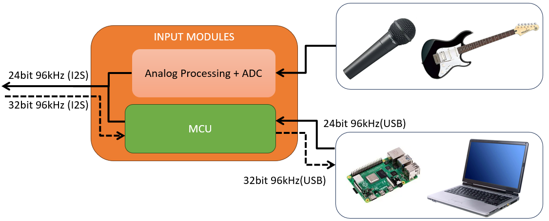
NB : the USB bridge only works as a slave. I have no plan on making it work with USB headphones, or USB microphones. I don't know how nor am I interested in that feature for now.
Also important is the fact that the USB bridge will probably be on this module : this allow clean cable management on a rack which is noice. unpopulated components will be placed on the main mixer PCB so that if you want only 2 USB devices and 4 analog inputs you don't have to buy 6 MCUs instead of 2.
Analog Processing - The Plan
As you can see, the Analog part has some processing in it, and it is crucial. Our analog devices might need phantom power, an attenuator, a pre-amp, the input might be balanced, stereo, mono etc.
The Input module is in fact the most important module because even if everything else works, if it isn't calibrated correctly the rest will sound like garbage : if the bridge doesn't work then no audio will reach the mixer/the user, if the analog part sucks then the processing won't give correct results etc.
The processing chain will look something like this :
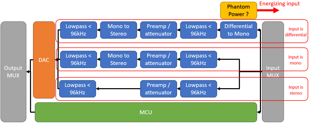
NB : the mono/stereo/differential path are just for visuals. The "mono to stereo" module is the same for mono and differential, the low pass filter is the same for each three path. depending on the user input selection, certain modules will be shorted and ignored.
Filtering is necessary to remove the aliasing that will come after the ADC.
If the user amplify a signal that is already large enough, it will clip and create harmonics that will also create aliasing.
To be honest, i don't know if both filters are necessary or only the one before the ADC. My small experience tells me to do both but i have no audio training and only saw it on highly specific metrology applications, way beyond the scope of audio. So, this will stay for now but if the OpAmps use are too expensive one might leave.
Analog Processing - Phantom Power
This will be short : most of it will be taken from this amazing tutorial by DJJules and its included references : https://www.instructables.com/Build-the-Four-Channel-SSM2019-Phantom-Powered-Mic/
Basically : you press the phantom power button and the inputs gets polarized to a specific voltage. He uses 15V, I have yet to decide what to use.
Analog Processing - Preamp
To be done : this part will be reused for other parts, so we will study this later.
Analog Processing - Attenuators
To be done, still have to check whether resistor cause too much noise vs using dedicated audio ICs ( it'll probably be resistors)
Analog Processing - ADC
This'll be short : I'll simply use an out of the box two channel ADC that outputs I2S at 24 bit 96kHz. That's all it has to do, and most modern ADCs are so good that most of the issues will be with my circuit, not the chip.
Digital Processing - Bridge
To be done : this part will be reused for other parts, so we will study this later.
Discussions
Become a Hackaday.io Member
Create an account to leave a comment. Already have an account? Log In.