Bottom Line Up Front
The data-line for ccTalk is on pin 4. The power and ground pins are on pins 1 and 3. Power and ground are identical on both the NRI connector and the ccTalk port. Like no-duh. Well, best not to make assumptions.
TL;DR
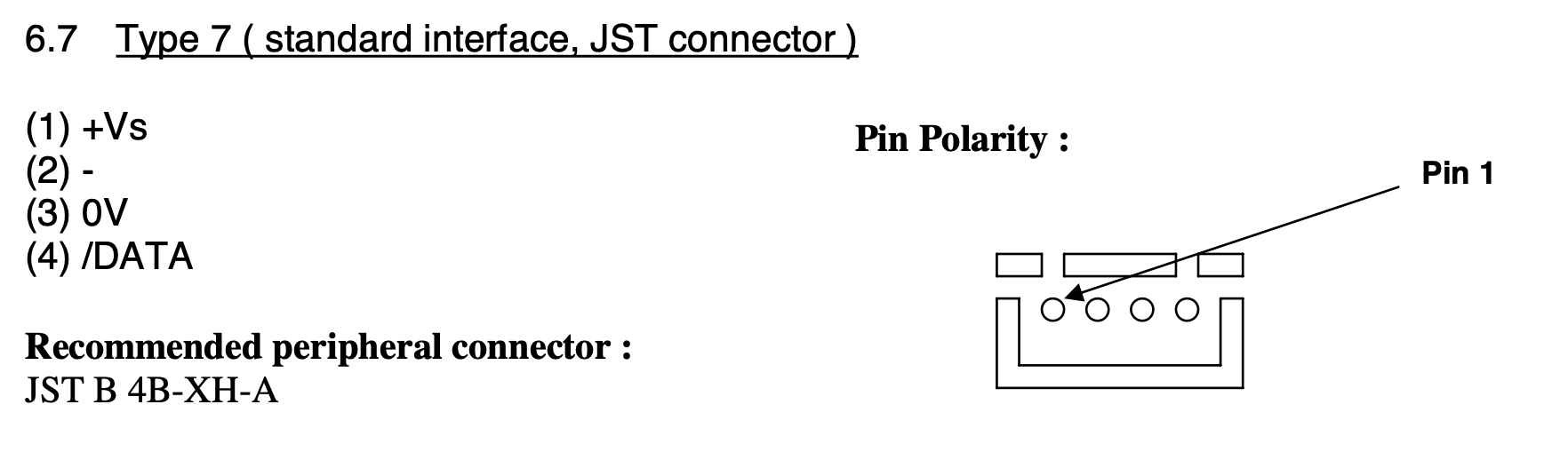
So I need to find the data-line for the ccTalk port. Reading part 1 of the ccTalk specification, we see that data is found on pin 4. And the directional locality (ok polarity) is also shown:
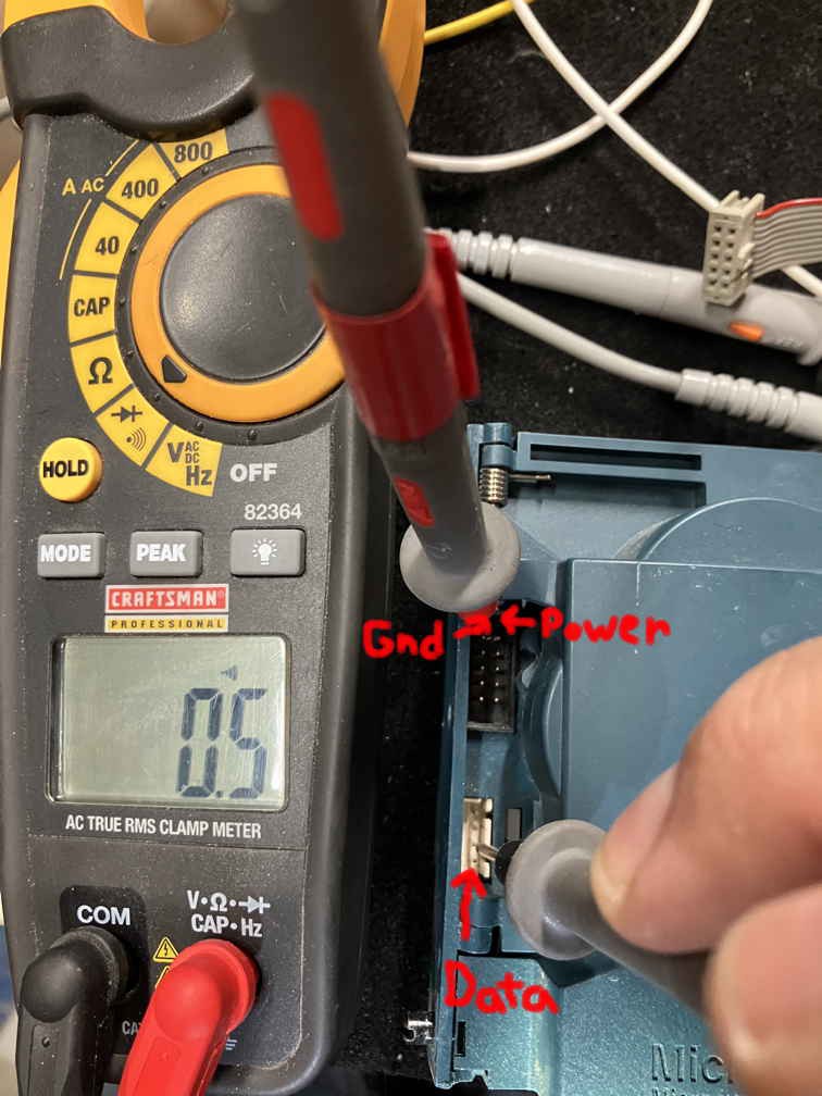
So what does all this mean in the real: Where's the data pin. Well, power and ground were previously found on the 10 pin NRI interface. I know that ground is on pin 1 (upper left) and power is on pin 2 (upper right) in the 10-pin connector, that is the NRI interface (ok the black plug on my coin acceptor.) Grab the multimeter and look for continuity. The figure below shows the red probe on ground (pin 1) and a probe on pin 3 of the ccTalk port (ok white plug). There's continuity so data is the bottom pin:
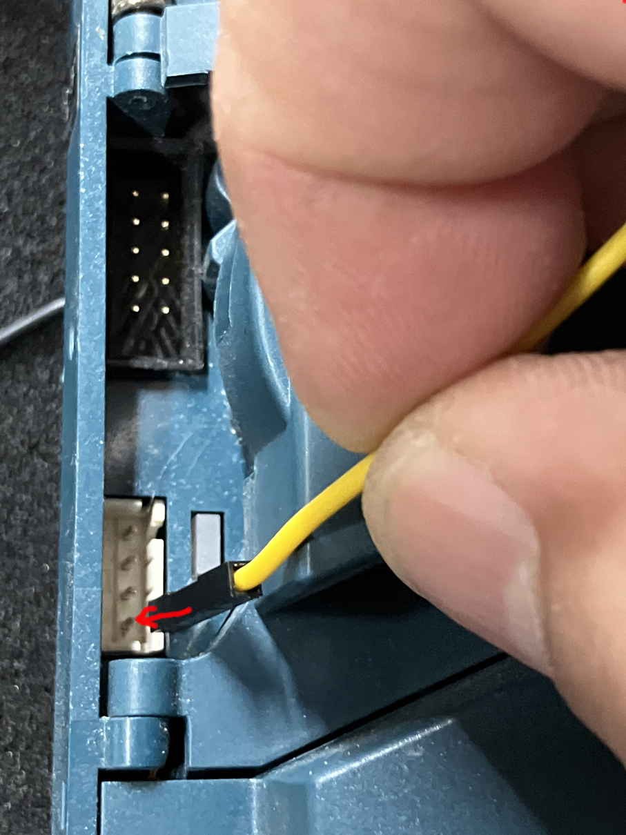
Currently, I supply ground and power via a 10-pin ribbon cable. I thus, use a simple connector to the data; just a wire from the parts bin and works good enough for my tests. As seen below, stick the silly connector on pin 4 for data. I will use this connector/wire when connecting the coin acceptor with my computer:
Discussions
Become a Hackaday.io Member
Create an account to leave a comment. Already have an account? Log In.