Bottom Line Up Front
Falstad is an on-line circuit simulator. It was used to simulate the ccTalk interface. The simulation confirms that the circuit couples and decouples data sent and received on the ccTalk protocol’s single data-line.
TL;DR
Measure twice cut once. While I am not building a wood cabinet, I believe the saying still holds. These days, you can simulate circuits on a laptop while watching TV. We truly live in a great time. So before I build the circuit with real components, let me simulate first.
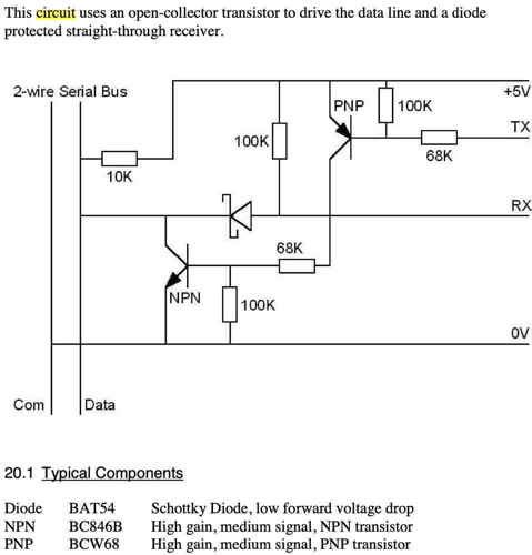
A quick recap: ccTalk is a protocol that lets a host like a PC or vending machine communicate (serially) with its coin acceptor. The protocol uses a single wire to transmit and receive data. The ccTalk specification thus, provides an interface to couple and decouple the transmit and receive signals from your (RS-232) serial adaptor. Last, the protocol uses +5V for the Mark state and 0V for the Space state. I found these class notes from U of Wisconsin on the basics of serial communication helpful. [ECE353]
Let me re-post the ccTalk interface circuit; it's from part 3 of the ccTalk specification:
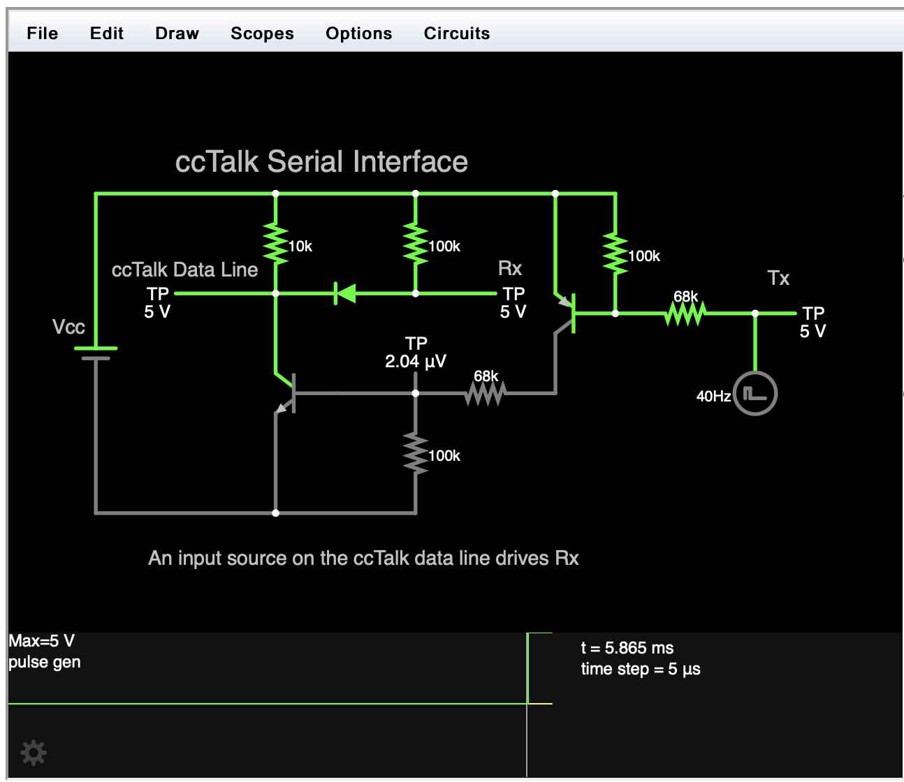
And its representation in Falstad:
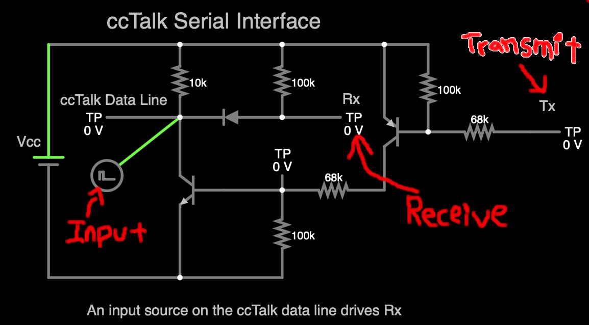
Here, I show three Test Points (TP): The ccTalk’s data-line, and the UART’s Rx and Tx lines. Note that that the input is an impulse function. It slowly steps between 0 volts and +5 volts, so we can see the what happens at Rx and Tx.
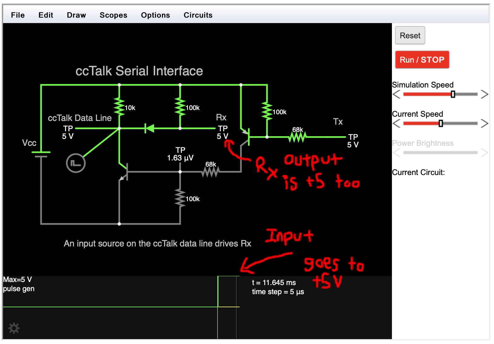
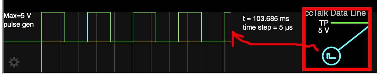
When the input goes to +5 volts, Rx is also at +5 volts. Observe that the Rx Test Point (TP) is 5V:
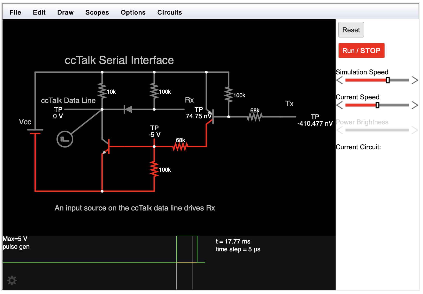
And when the input goes to 0 volts, Rx follows: Observe that the Rx TP is now at 0 volts. OK, pretty darn close enough to exactly 0. Last, the tool depicts the impulse function is as a green-rectangle along the bottom. I think Falstad calls it a 'scope':
Of course, if the simulation runs for a longer time, the input (OK scope) on the data-line will alternate between +5 and 0 volts (logic 1 and 0). So why use an impulse function? It simulates the eventual transmission of arbitrary binary data by a coin acceptor. ??? Imagination, while the function just goes 101010... I imagine it being arbitrary data.
☞ Clearly, we want the Rx line to track what the coin acceptor is sending on the ccTalk data-line. However, I observe that the Tx line is also following the data-line. Now I’m a software guy, and am assuming that this is OK. That Tx is only a transmit register, that the UART’s circuitry is capable of sinking current placed on its Tx pin (there’s a 68K ohm resistor, so not even a 1mA.)
Finally, lets track what happens when the UART transmits. Below, please notice that the impulse function was moved to the Tx Test Point (TP). It still cycles between +5 and 0. As expected, when a +5 is sent, the data-line is also at +5.
☞ Like I mention above, please note that the Rx test point tracks what is on Tx. I assume that this is OK. When the UART is transmitting, it won't accept (read) the data on its Rx pin. Yeah, I realize that a serial connection might be full-duplex. So the UART might re-read what it sends. But for now, I must assume the designers of the protocol knew what they were doing and use what they offer.
Ok, the post is getting quite long. So instead of showing that no voltage at Tx is matched on the data-line, let me just Post my Falstad file.
I’m close. I’m nearly ready to hookup the computer, it’s serial lines, the interface circuit, and the coin acceptor. But first…
The link to the Falstad circuit simulator:
Discussions
Become a Hackaday.io Member
Create an account to leave a comment. Already have an account? Log In.