Bottom Line Up Front
The ccTalk interface circuit. was built on a breadboard with a few components. This was straight forward. Well almost.
TL;DR
I substituted the following components for those specified. If it didn’t work, I’d have simply ordered the right part. But since the resistors were really only being used as switches, and the resistors only being used as voltage dividers, I was fairly confident it’d work:
Component | Specified | Substituted |
Schottky Diode, low forward voltage drop | BAT54 | 1N5817 |
NPN, high gain medium signal transistor | BC846B | 2N4400 general purpose |
PNP, high gain medium signal transistor | BCW68 | 2N4403 general purpose |
Resistors ¼ W | 68K | 57K |
And the breadboard:
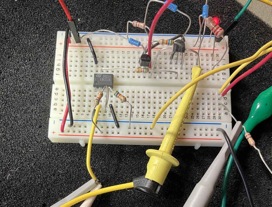
And it did not work. Recall that my serial adaptor only outputs 3.3V. The interface circuit is designed for 5V. Now, I could include an image of the wonky signals from the oscilloscope, but let’s move along. I inserted a voltage comparator in between the adaptor’s Tx and the Tx of the ccTalk interface circuit.
Discussions
Become a Hackaday.io Member
Create an account to leave a comment. Already have an account? Log In.