 Kevin LO
In this project, we are trying to drive a BLDC motor in very low speed. This means we need to have a very low PWM values update rate. However, the PWM values update rate is constant, the rotating speed of motor's rotor may not being what you expected. It will not spin with constant speed.
We are facing a cogging torque of electrical motors. It is a due to the interaction between the permanent magnets of the rotor and the stator slots of a permanent magnet machine. This torque is position dependent and its periodicity per revolution depends on the number of magnetic poles and the number of teeth on the stator.
Cogging torque is an undesirable component for the operation of such a motor. It is especially prominent at lower speeds, with the symptom of jerkiness. Cogging torque results in torque as well as speed ripple; however, at high speed the motor moment of inertia filters out the effect of cogging torque. (Check the right un-calibrated motor in the given video)
In order to minimize cogging torque, we will use a variable PWM values update rate, to drive BLDC motor. With a lookup table maps to rotor's mechanical rotation angle, we will have different time delay to update the PWM values to the motor. A calibration program is needed to find out the values of the lookup table.
Program:
For the calibration program, it fills the lookup table with constant value first. The main loop() of the program will get readings from AS5600 sensor board, in every 20ms. The goal of calibration is to obtain one count of delta change of angle from the sensor within 20ms. If it is more than 1 count, it increases the corresponding value in the lookup table. If the count is zero or negative, it decreases the value in the lookup table, mapped with last angle read from the sensor.
The PWM values update at a rate given in the lookup table, while the lookup table is update on the fly. When no. of iteration is reached, the calibration process will terminate and print the lookup table. You may copy and paste these values into you own program.
In the Demo program, it uses the two lookup table as PWM update rate to drive BLDC motor. The rotor spins from slow to fast, then slow down and rotates again at another direction.
Construction:
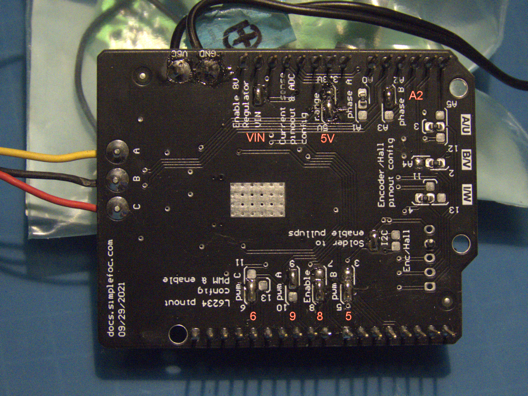
1. Select the options on the Sample FOC Shielded board:
2. Mount the Simple FOC Shielded board on the Arduino UNO board:
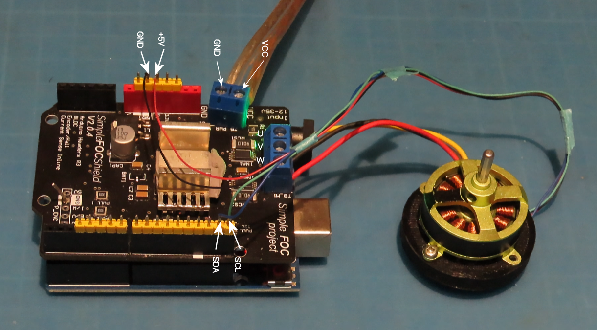
Connect +5V power lines and I2C interface from the AS5600 sensor board to Simple FOC Shielded board. Connect the main power supply to VCC and GND. For the BLDC motor, the main power supply is +12V dc.
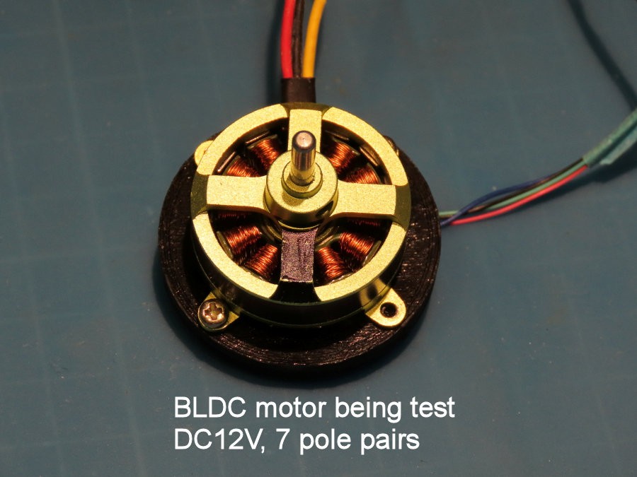
3. The BLDC motor:
4. The magnet mount on the rotor of this motor:
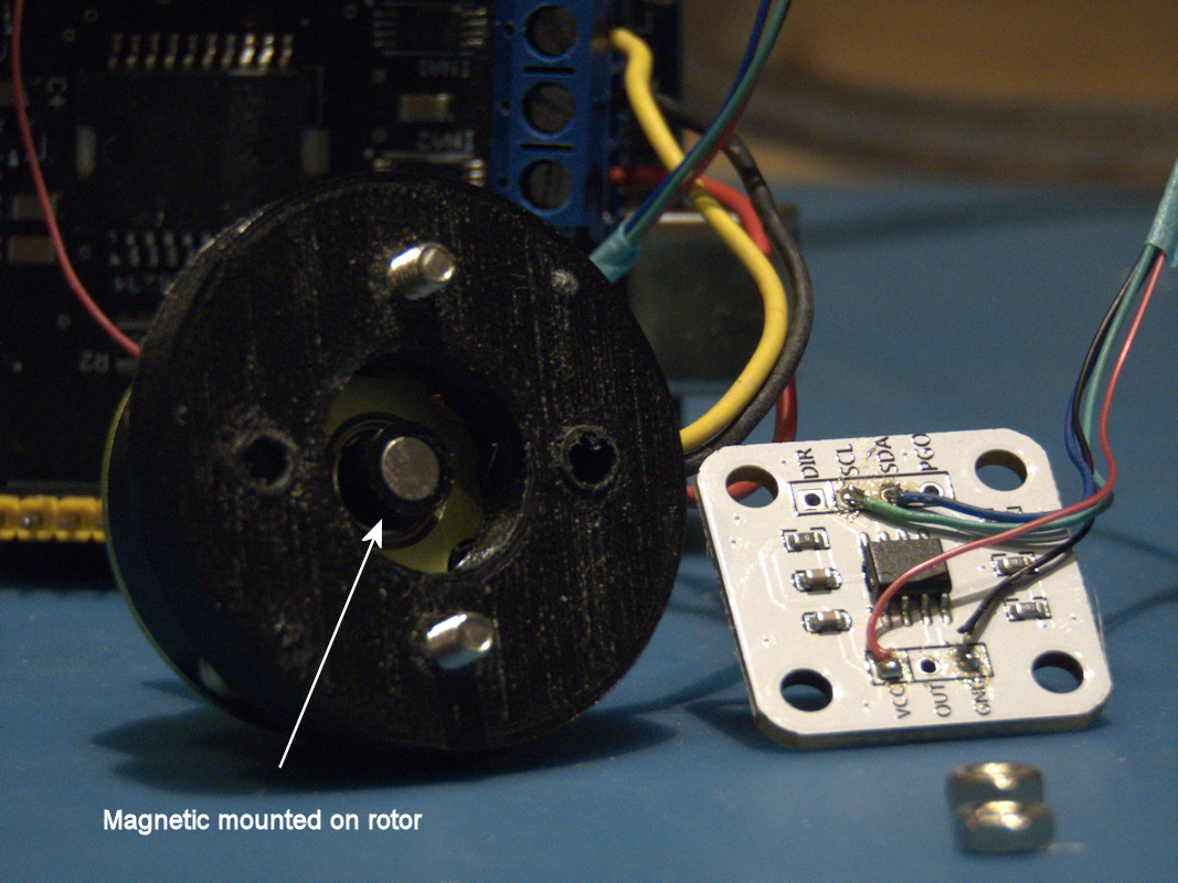
5. and the AS5600 sensor board mounted on the back of the BLDC motor:

Video:
This video shows difference in between un-calibrated and calibrated motor is driving at low speed.
Usage:
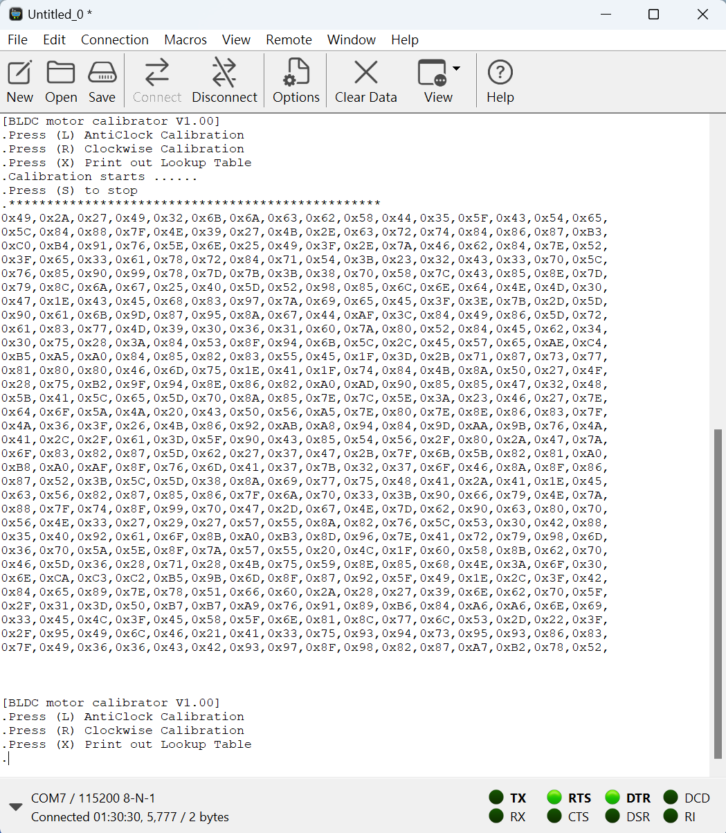
Use coolTerm.exe program in Windows, please configure the Baud rate to 115200. After reset, a simple main menu will show.
Press 'R' to calibrate the clockwise direction
Press 'L' to calibrate the anti-clockwise direction
Press 'X' to printout the lookup table
While during calibration, and '*' tells you one iteration is done. You may press 'S' to stop it. The lookup table than show up.
Note:
The no. of iteration is defined as "ITERATION" in the calibration program. You may change this value. However, greatly increase no. of iteration may not have a good result when most of values in the lookup table goes to its maximum or minimum value.
For better result, you may need to adjust the value of "MOTOR_DRIVERPWR", on both programs. This controls the driving current to the BLDC motor. What I suggest is about 30% to 40% of maximum power needed.
==================================================================
Hoping this project may help you.....
Please feel free to send me advice or questions.
 Krockwell
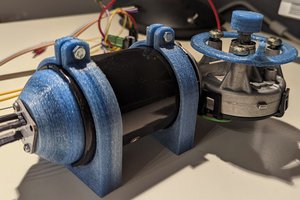
 JP Gleyzes
 Frank Herrmann
 John Taylor