This project is designed to for kids. My meetings are usually about 1 hr 30min long, this project will take four meetings. I have a group of about 10 kids participating. There is a lot of soldering, I get parents to help. I can spend a lot of time trouble shooting soldering issues. Recommend having a good de-soldering tool :D I also have several soldering irons this helps keep things moving.
I recommend breaking the group up in half. One half works on the soldering and the other group works on the box. There is more to the box than it seems. I store the box with weight on it to prevent warping. I laser the box before meetings. Main reason is my laser is in my home workshop and the meetings are in a different location. First you need to glue the magnet in place. I don't use super glue, it's fast but I don't like the fumes. I use wood glue. Important make sure they are putting the magnets in the correct orientation. Once this is down they can assemble the box. The tricky part is to put in the triangle parts. The glue for the magnets will still be drying. I use four rubber bands to hold the box together (two near the bottom and two near the top). Then put a "Small" about of glue around each edge. Remember a little goes a long way. I have the kids use an ear swap to spread the glue. Make sure to also glue the magnets on the lid, remember the +/- of the magnets is important. This needs to completely dry.
The other group will be working on soldering. First I have the solder the headers on the shield board, cut out the correct header length. put the headers in the arduino. then place the shield board on the headers. Check to make sure correct before having them do any soldering. Then have them solder a header on the board for the RTC (I've included URL below). Soldering the wires on is a bit tricky for the kids.
https://www.pishop.us/product/ds3231-real-time-clock-module-for-raspberry-pi/
At the first meeting. I explained that we needed to think about our project and identify areas that might be a problem. I used a white board to list out Unknown, I then asked them questions; example: can we change the meters to work off 5v ? we then added this to the board of under Unknown, I asked them if a PWM signal could control the meters.... added to the Unknown list, Faceplates for the meters added to unknown list, how do we get the arduino to know time added to the unknown. As we moved through project I would remind them that we had just solved on of the "unknowns". I had the kids take the meter apart, first explaining that it was delicate. I measured the existing resistor that was in the meter and explained what Oms law was and why it was important, and how we could use it to find out how to drive the meters at 5v (arduino). Then I had them cut out the existing resistor, I soldered in the replacement and a parent help (that part is pretty trick solving for a beginner).
At the next meeting. I introduced everyone to the Arduino IDE, explained that it was free to download. Showed them how to select the board and the port. I had selected original arduino's verses clones so they would be easier for the kids to use. The original arduino's will display the name "arduino" in the USB list. With clones you have to test each item listed in the USB list.
I used the code "clock-PWM-test", I hooked up and Oscilloscope and I explained what a PWM signal was and what they were seeing, and how the code was controlling everything. I asked them what number would put the needle at 75%, then 50%, they caught on very fast.
I gave them "home work", they test code only worked for one meter, I asked them to see if they could update the code to work for two meters.
Lessons...
Read more »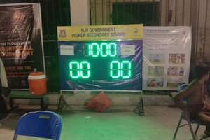
 ZaidPirwani
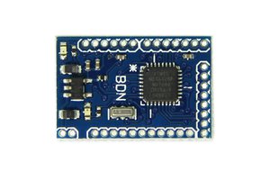
 Niek
Niek
 Benjamin Blundell
 DigiGram