 decle
decleThis post details the approach that Sean Riddle and I took when dumping the code contained in the Science Fair Microcomputer Trainer (SFMT) back in 2015. This built on previous work by Kevin Horton (aka Kevtris). Although I'm writing this up, credit should go to Sean and Kevin. If this description inspires you to try ripping apart your favourite 1970s toys and microwave ovens to dump the firmware, I'd encourage you to check out Sean's website to see if he's done the hard work for you already.

The SFMT is based around the TMS1100. This is a derivative of the TMS1000 microcontroller released by Texas Instruments in 1974. The TMS1100 has a 4-bit CPU, 2K of ROM and 128 nibbles of RAM housed in a 28pin DIP. In the SFMT the firmware in the 2K ROM contains an emulator of a 4-bit virtual machine, and seven "games". It's quite impressive.
Dumping the firmware out of the ROM within a TMS1xxx is theoretically pretty simple. Fundamentally, there are two approaches.
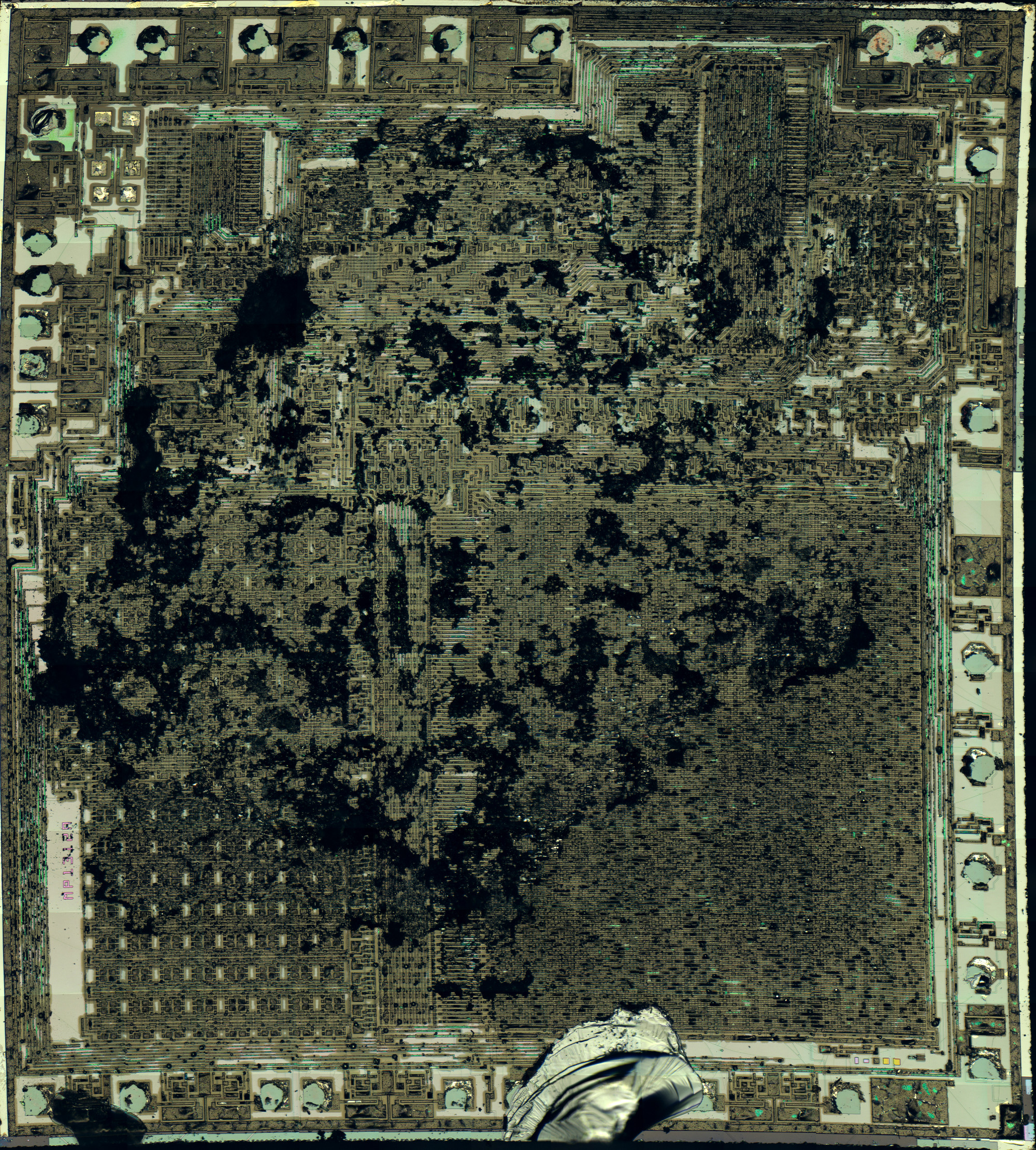
- Take your TMS1xxxx and grind the top off the package, exposing the die. Photograph the die. Remove the top metal layer from the die using acid, and photograph it again. Reverse engineer the ROM contents from the die images. This approach has the downside that it's pretty hard core and destructive, but it's comprehensive and is guaranteed to work.
- Observe that US patent 4024386, which describes the TMS1000, details a test mode that can be used to extract the ROM contents from the pin O7. Reverse engineer this process which starts at column 27, line 20, and read the ROM contents electrically. Whilst this is non-destructive, it has a number of drawbacks. Firstly, the summary of the test mode in the patent is incomplete and somewhat confusing. Secondly, in addition to the ROM, the TMS1xxxx allows customisation of two other aspects of the processor, the instruction PLA and the output PLA. The test mode does not allow these customisations to be inspected. Finally, over time Texas Instruments made changes to the TMS1xxx design to cripple the test mode. Whilst it is possible to dump early chips, by the time the TMS1100 used on the SFMT was in production the method detailed in the patent would only dump 7 bits of each instruction, and it is believed that the even later chips disabled this technique altogether.
In the case of the SFMT, Sean had already followed the first method, but in the process of decapping the chip the die had been damaged. It was early in Sean's decapping career and this happens sometimes, but as a consequence he didn't have a complete picture of the ROM. I didn't fancy destroying my SFMT, so we investigated reconstructing the work done by Kevtris to make use of the second method.
After some fiddling, we came up with the following circuit that could be connected to an Arduino or similar that would allow us to exercise the TMS1100 test mode:

In this case I used an Arduino Micro to control the TMS1100, using six transistors as inverting level shifters up to the 9V PMOS logic used by Texas Instruments. These are used to drive the clock, INIT (reset) and four K input pins. ROM data is then read out of the O7 pin. A couple of resistors are needed on O7, one to pulldown the open collector output, and another to protect the Arduino from the 9V logic of the TMS1100. The only other wiring necessary is power and a connection from the R10 output (confusingly labelled R6 on the SFMT) to +9V. @Jason Jacques has subsequently found that it's possible to undervolt the TMS1100 and run it at 6V, bypassing the need for level shifting and allowing it to be connected directly to an Arduino. Obviously, both the TMS1100 and Arduino are technically out of spec at this point, so your mileage (and damage) may vary.
We then use this Arduino program to dump the ROM. This clocks addresses into the K input pins using the rather strange protocol required by the TMS1xxx, clocks the resulting data out of O7 and reports it over USB to your PC. I won't describe the details of the clocking mechanism here, the truth is in the function getData() for those that are interested.
As mentioned earlier, this will get us 7 of the 8 instruction bits (a copy protection FET on the die ensures bit 8 will always read high). In our case we were lucky and bit 8 was intact in Sean's original image. He was able to use this to provide the missing 8th bit. More generally, it may be possible to infer which of the 8th bits should be high because only TMS1xxx call and branch instructions assert this bit. Therefore, if it is initially assumed that all instructions are not branches or calls (bit 8 is low) it might be possible to assess the plausibility of each instruction actually being a branch or call in turn, based on the nature of the code at the implied target address. Happily, Sean's image meant this potentially error prone approach was not required.
In terms of understanding the TMS1100, that leaves identifying any customisation of the instruction and output PLAs. For the instruction PLA, disassembly has not indicated that there are any customisations to the TMS1100 instruction set. I suspect that typically there isn't much call to alter instruction behaviour, and this is the normal state of affairs. Disassembling the firmware also allows us to infer the contents of the output PLA. In the SFMT it's very similar to the standard 7 segment display setup described on page 2-21 of the TMS1000 Programmer’s Reference Manual. The minor differences to support keyboard scanning can be worked out from the reverse engineered code.
Now, armed with this powerful new knowledge, it's possible to write an emulator of the SFMT...
Discussions
Become a Hackaday.io Member
Create an account to leave a comment. Already have an account? Log In.