 Bulbul
Project Log #2
A bigger cap and a sandwich
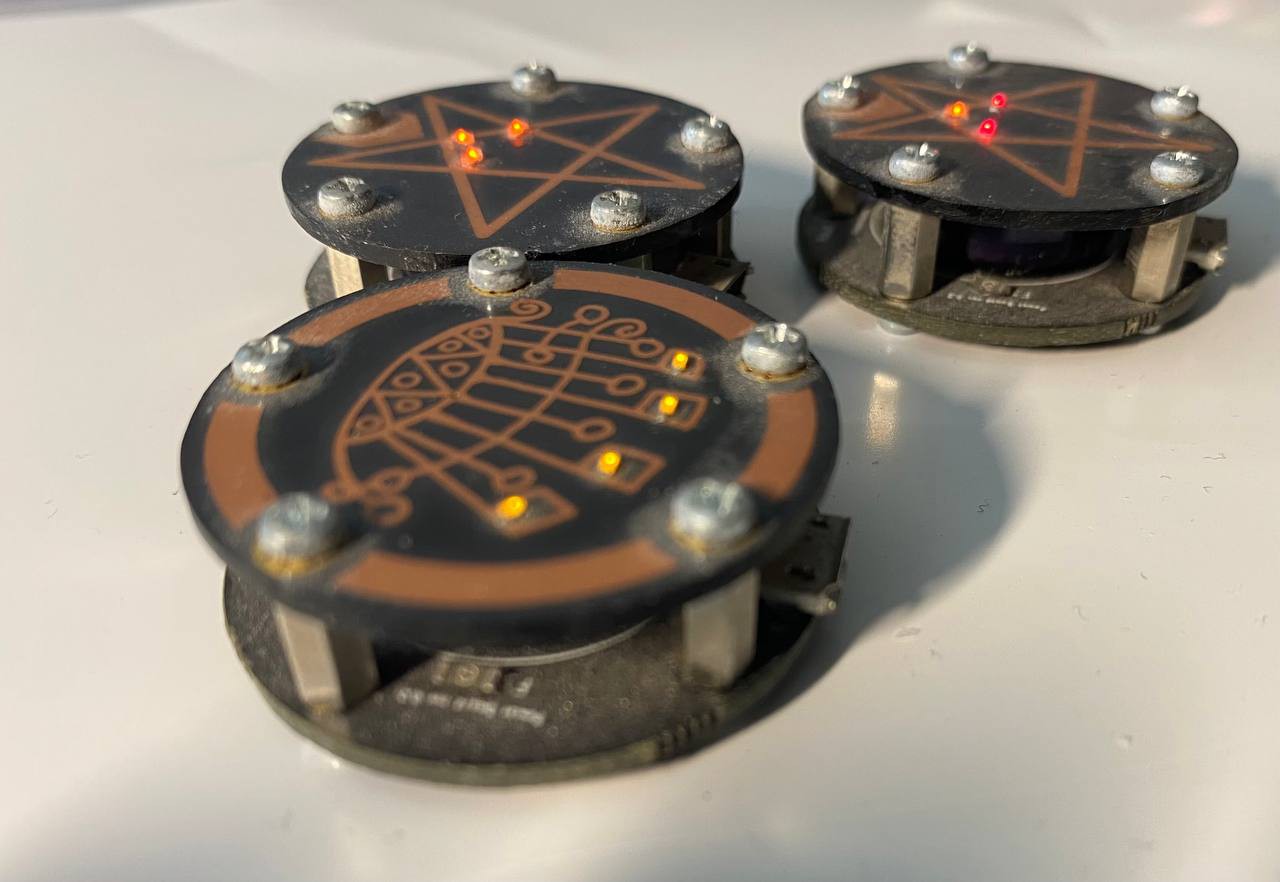
So after the terrible ??? circuit of the first one I switched my focus to finding a better power source. When trying to design something a lot of my time is spent on a component distributor website, looking up parts in the parametric search, filtering and sorting by various criteria. In this case I was looking for the a good tradeoff between physical size and capacitance for EDLC. In the search I found some some short height radial can EDLC caps rated at 1F (and also 1.5F). Once again not wanting to do straight math to find super accurate run times, I decided just to play around with some. The one thing about these caps is that they are THT. This would be difficult to have a nice undisturbed art board if I placed it on the back of the pcb like I did with the smaller SMD EDLC in my first amulet attempt. This gave rise to the sandwich case idea, where one board managed the power and one board had the design, started (eventually evolving into the baseboard /face plate idea). I was excited about the idea because it lent itself to being modular, I could swap front facing designs! Once I thought about that it started being more than a one off gift, it felt like way too cool of an idea to just leave alone and not want to get other people in on.
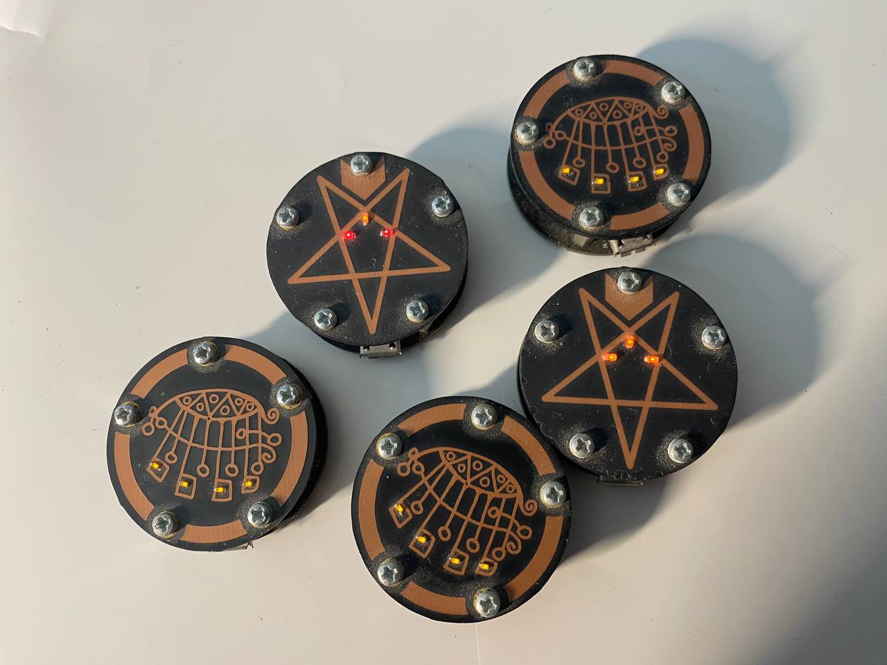
So now that we have the sandwich, the next step was the circuit. The caps were rated for 5.5 volts which meant I could charge them easily from USB, the only thing to worry about would be drawing too much power so I just threw a resistor in series to keep the max current set. I played with a couple ideas, in the end decided using a buck-boost would help keep led light consistent. Next was figuring out how to send power and connect the two boards. The easiest solution was to just use the standoffs for power and ground connections. I layed them out in a star shaped pentagram pattern and used the top stand off for power and the other four standoffs for ground.
Another addition was a buck-boost, since the cap would charge at 5 volts and discharge to based on required voltage and load it was a pretty wide range and the brightness of the leds in any design would vary greatly over it's runtime. Easiest way to do this was to use a buck-boost voltage regulator to output a consistant voltage. Most LEDs can work with a forward voltage of 3 volts so I decided to set it on that. I had to use 0402 to squeeze everything in nicely which wasn't a big worry at the time of design. So depending on leds in the face plate design led runtime was usually 30-50 minutes with charge time being very very fast (yay supercaps!). If i remember correctly there was at least one attempt at this design before this board where I had severely under-speced the inductor, leading to some burn outs. I was still learning! this was my first time using a switching regulator and inductors believe it or not!

Improvements over first attempt:
- actually worked!
- can have modular designs
- usb charging
- runtime increased from seconds to ~30 minutes
However there was one problem in combination with some other factors that led me to look for other solutions. Thanks to my standoff power carrying design If you set the amulet down on any conductive circuit, it would short! I luckily didn't find this out the hard way and it's something that I had an "oh derp" realization moment. Not satisfied with that I decided to keep plugging away and searching for alternatives. But not before making at least a couple different designs.


Discussions
Become a Hackaday.io Member
Create an account to leave a comment. Already have an account? Log In.