0%
0%
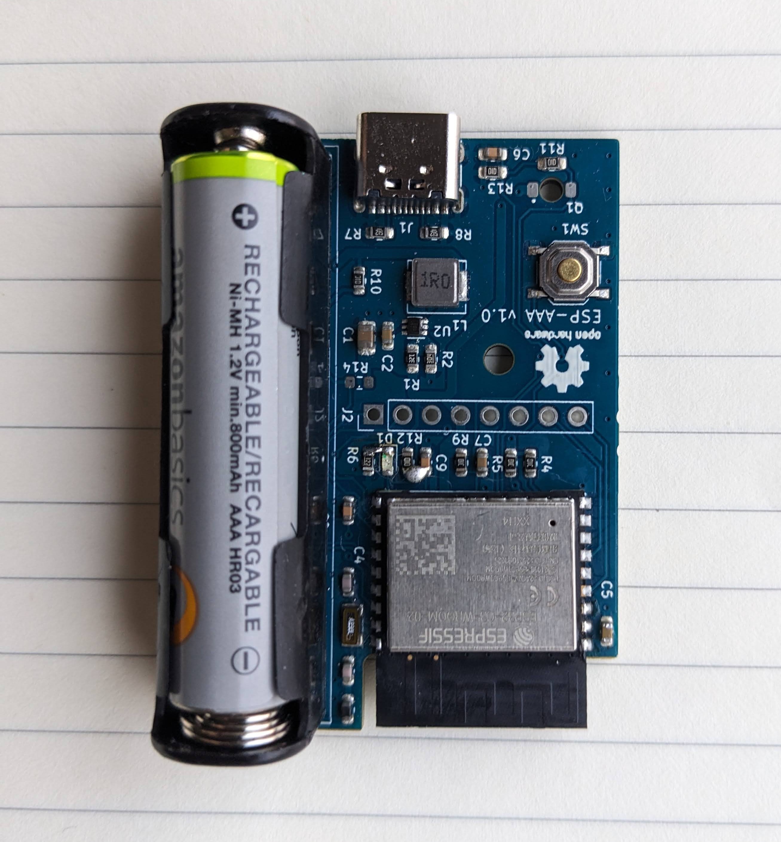
Battery powered LED pulse counter
A battery powered WiFi light pulse counter for household energy monitoring.
 Theo
TheoBecome a Hackaday.io member
Already have an account? Log in.
Just one more thing
To make the experience fit your profile, pick a username and tell us what interests you.
Pick an awesome username
hackaday.io/
Your profile's URL: hackaday.io/username. Max 25 alphanumeric characters.
Pick a few interests
Projects that share your interests
People that share your interests
 The current config used for esphome.


 Open Green Energy
 Vince
Vince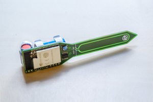
 Maakbaas
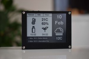
 Boris Shabanov
I will definitely watch progress on this one! There are ready to use designs available but AFAIK none battery powered.