 Keith
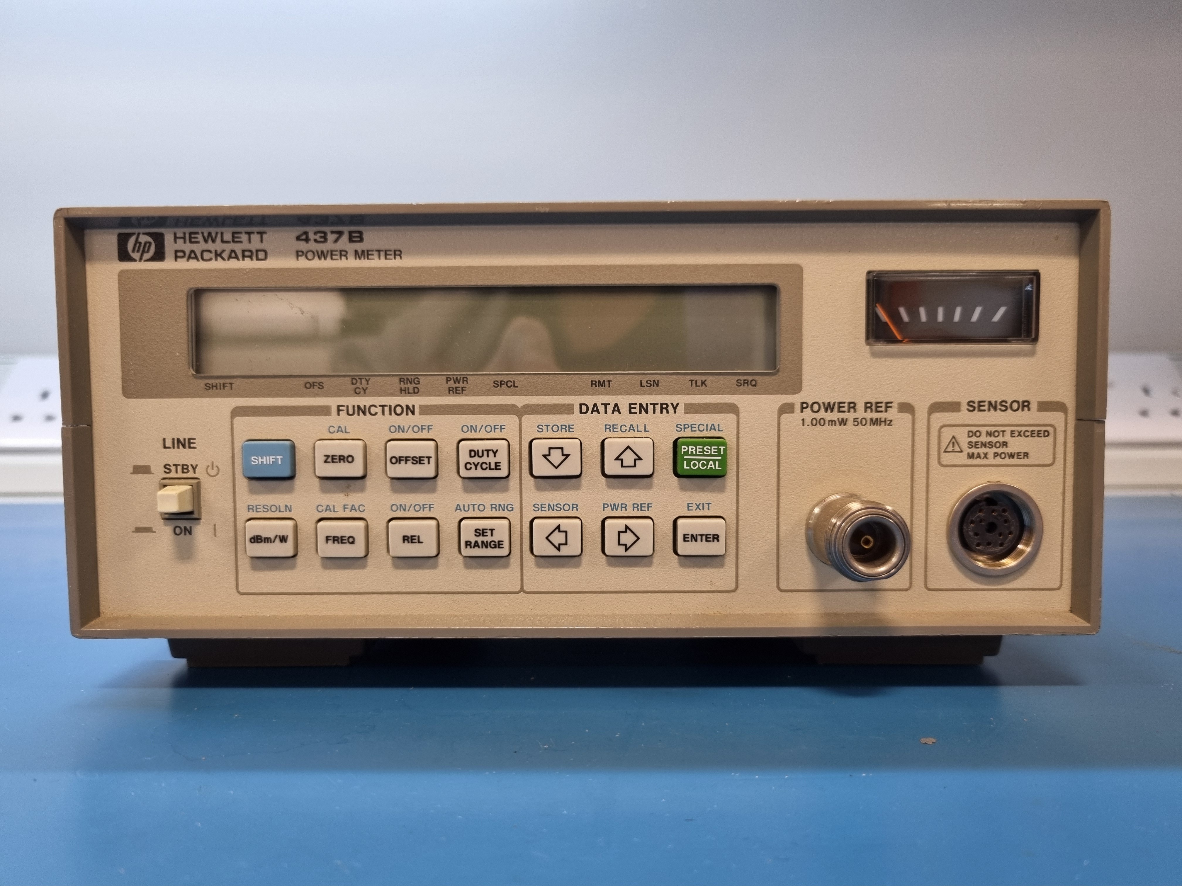
KeithFront view:
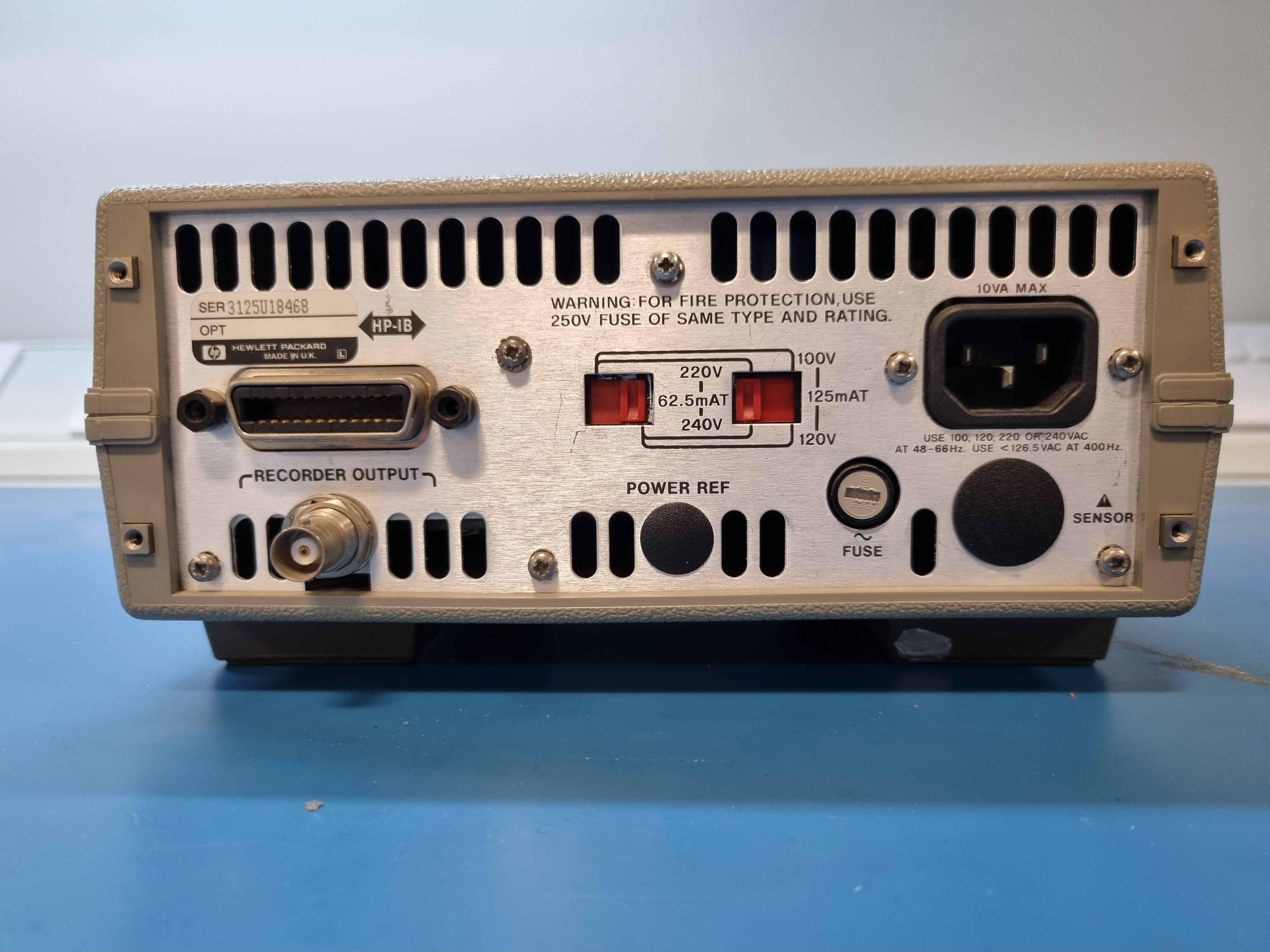
Rear view:
Bottom view, feet;
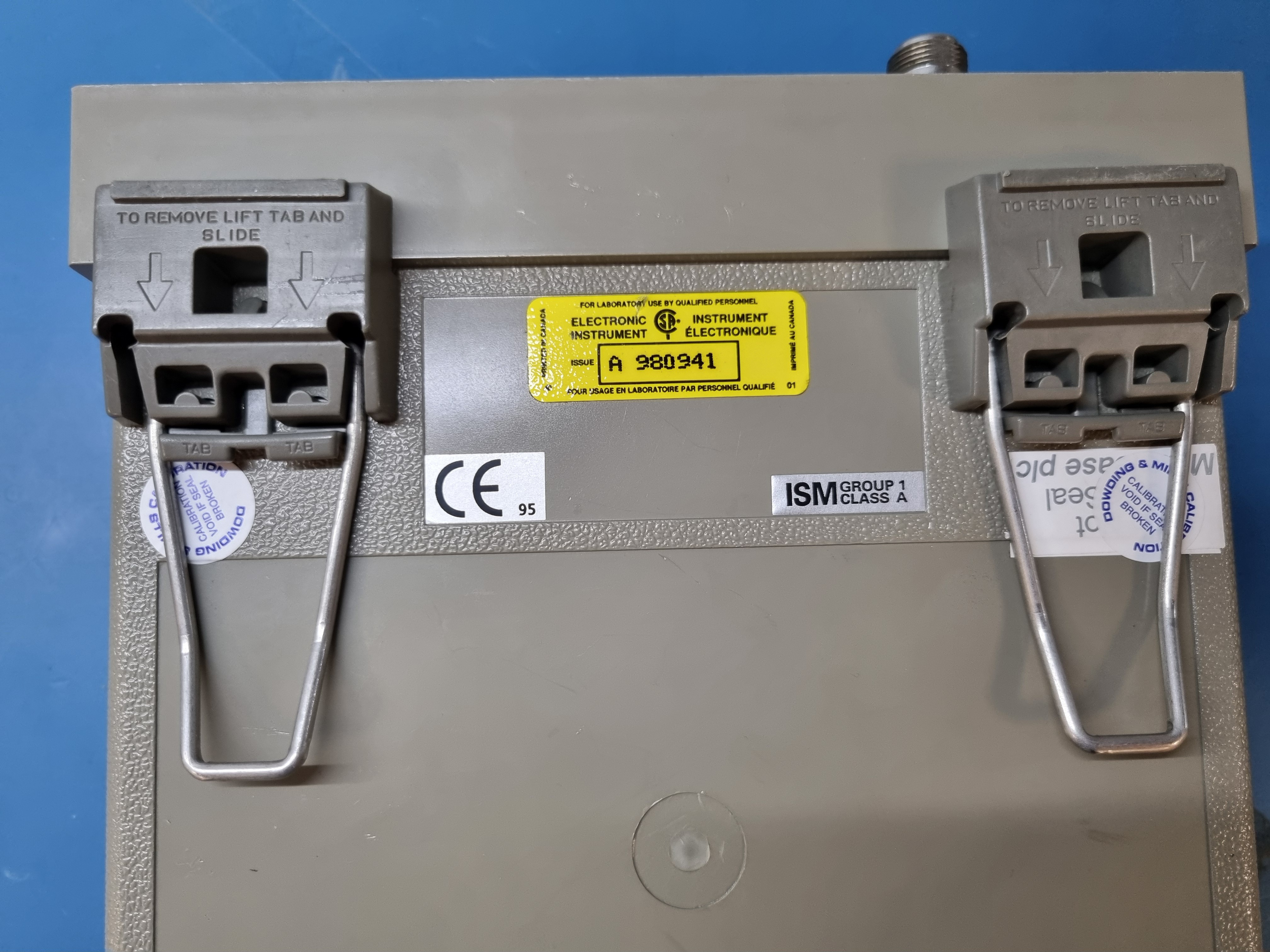
Two screws were hidden under the round calibration labels.
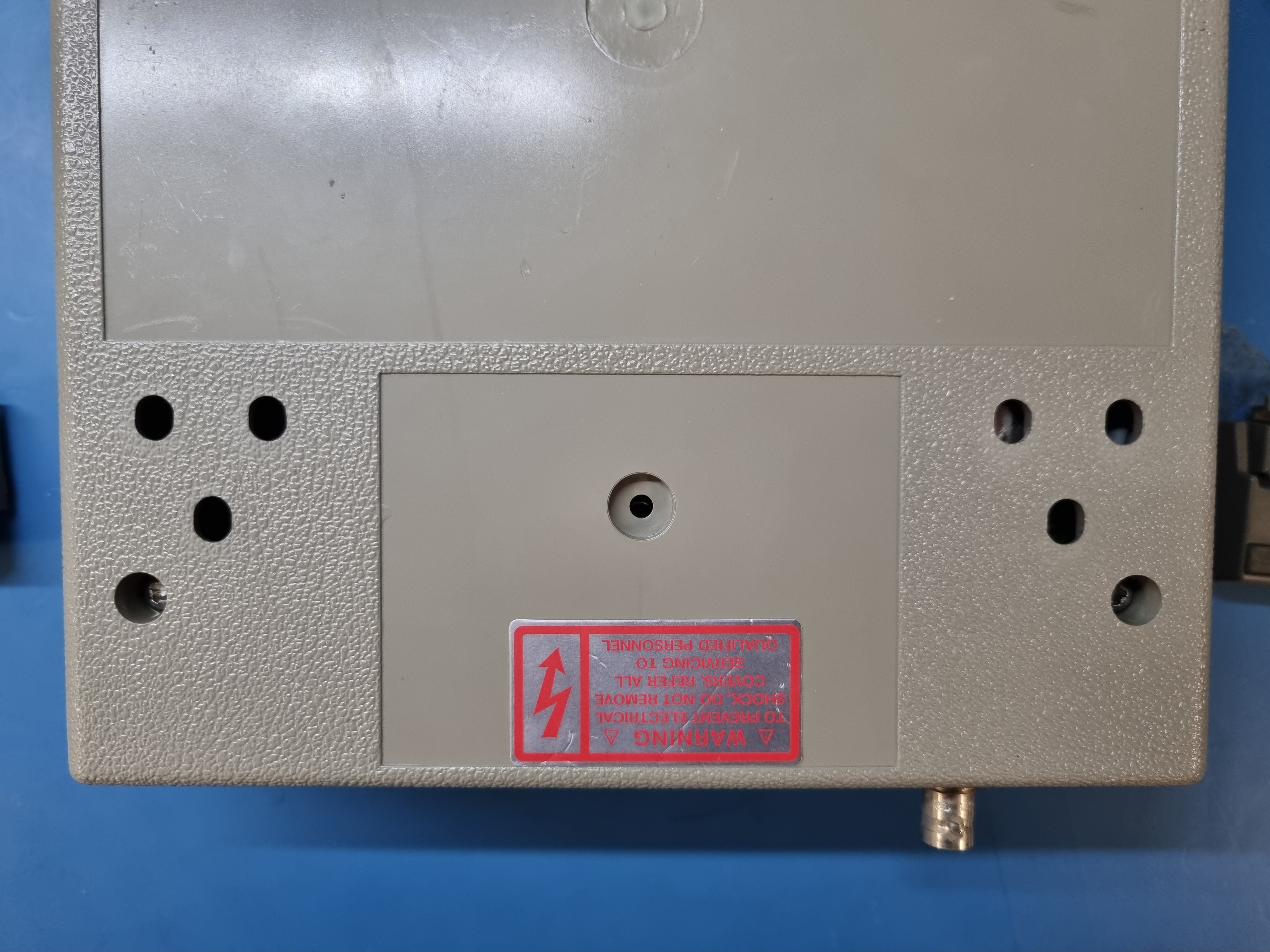
Bottom view, two rear screws hidden under the feet:
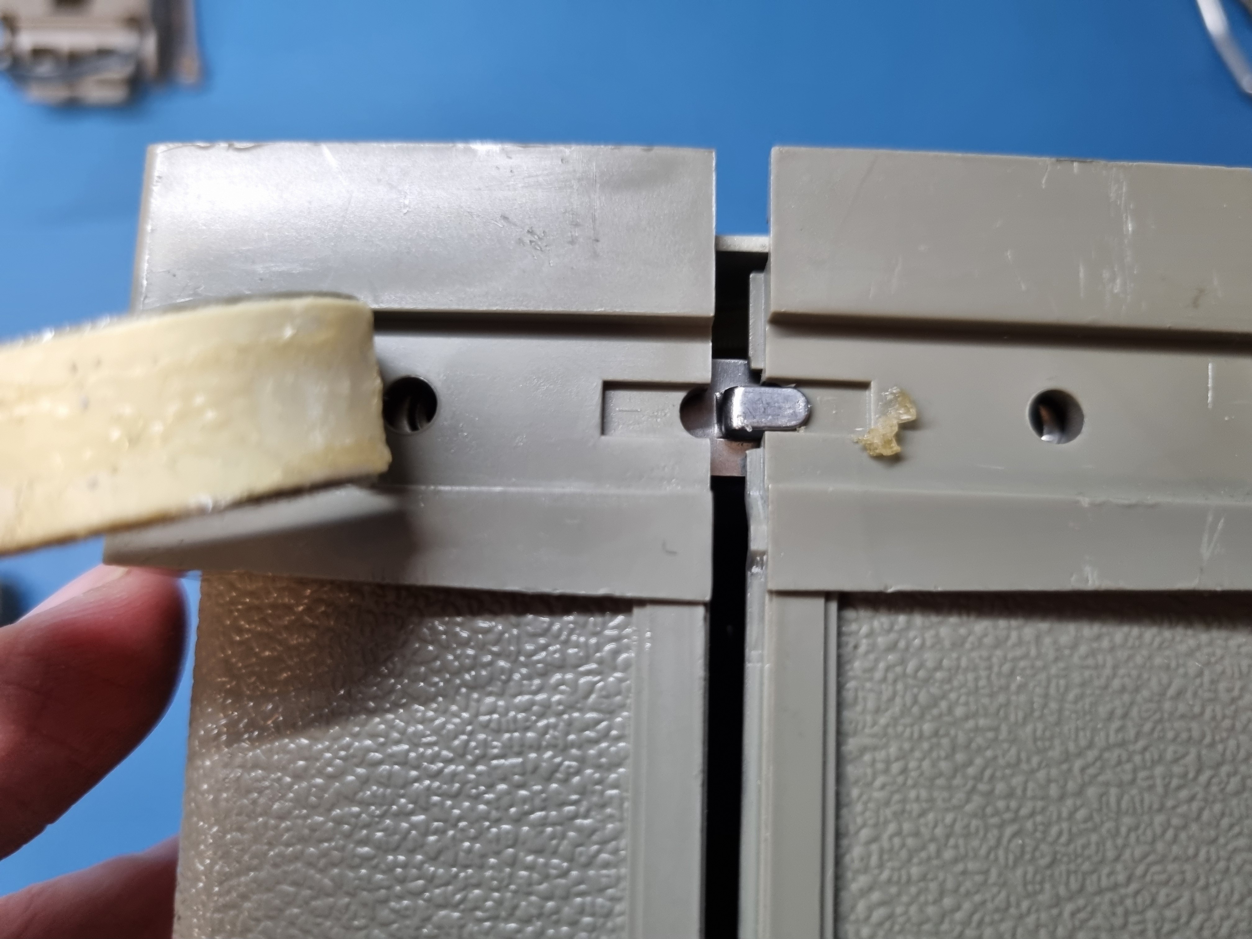
Side view, pull the sticky bits off:
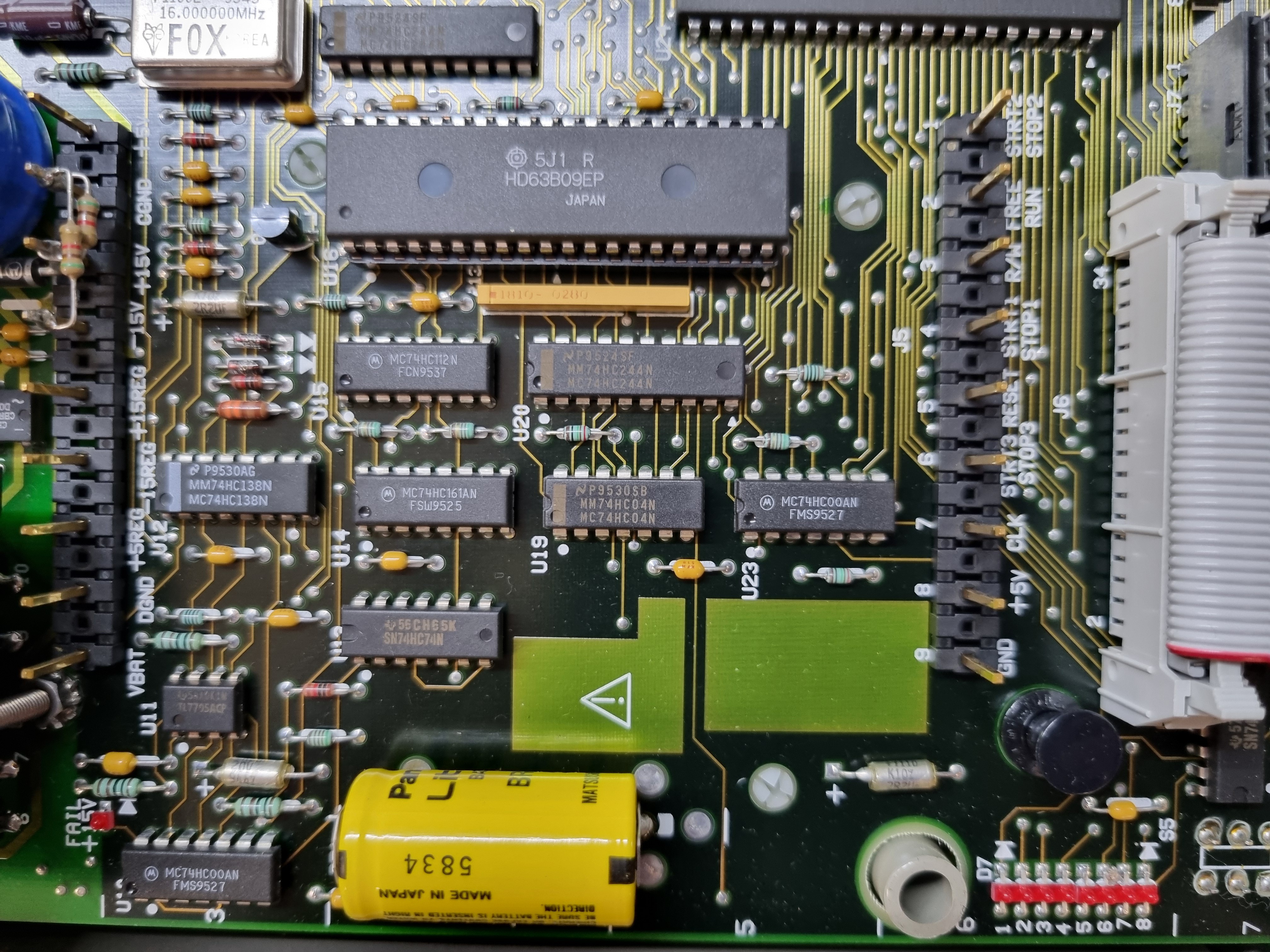
Complete top board:
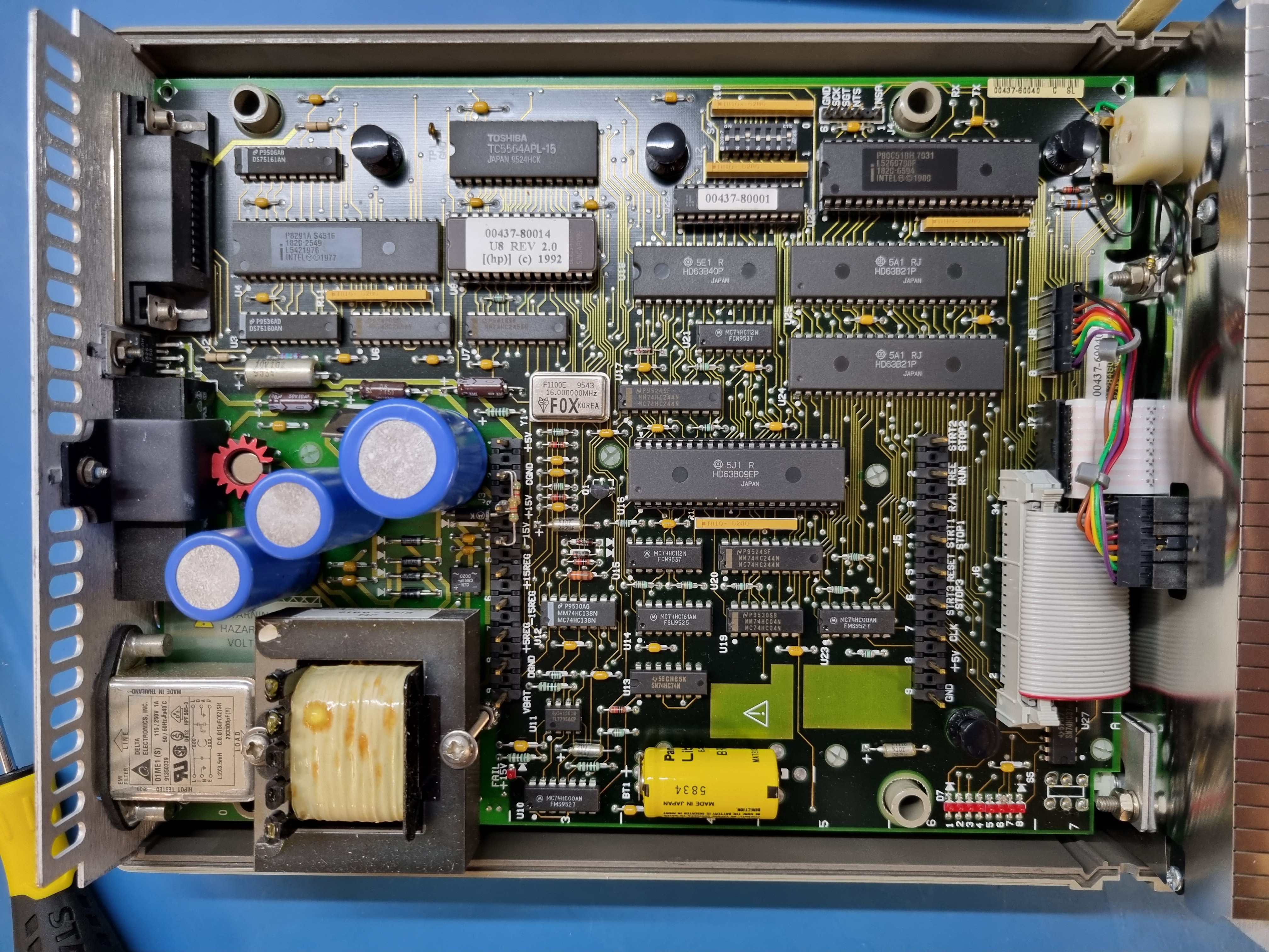
Ooh look, a 68B09E. The 63B40 is a programmable timer module serial I/O and the two 63B21 provide parallel I/O.
I don't know what the 80C51 microcontroller does. Maybe helps manage the front panel?
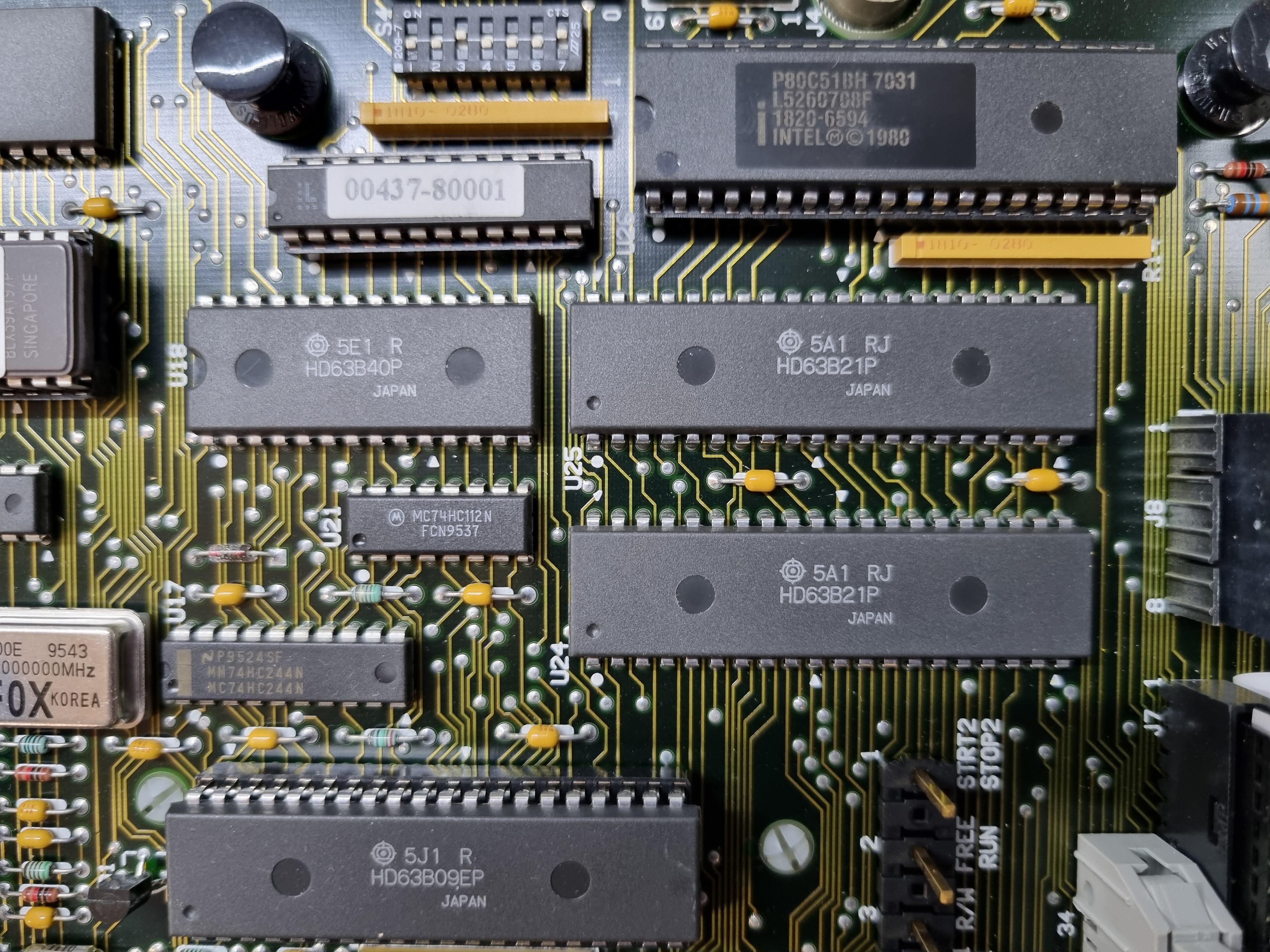
The oscillator is 16 MHz.
ROM (8k), RAM (8k HN27C64) and the IEEE interface:
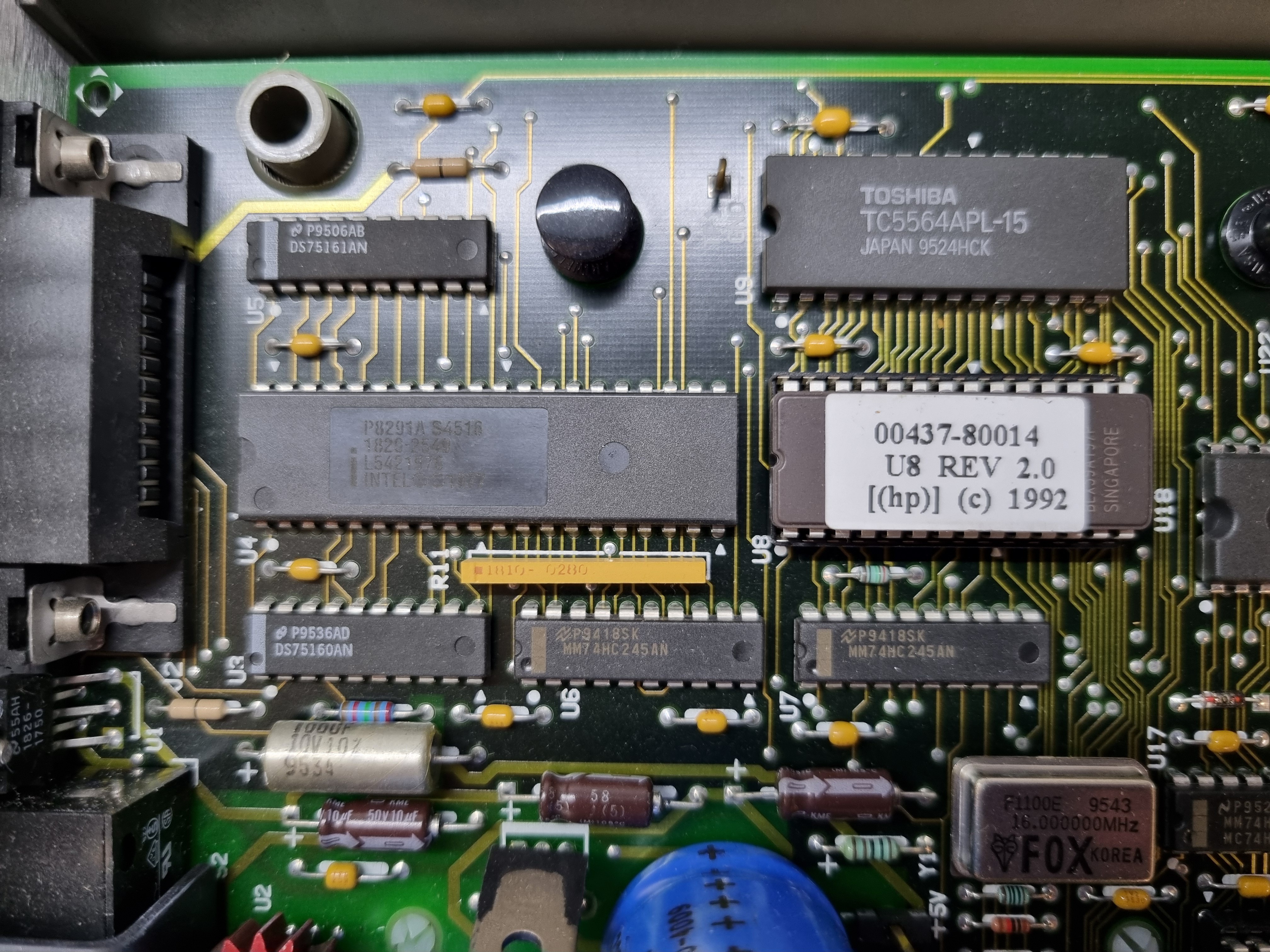
The intel P8291A is the IEEE488 talker/listener interface, the DS75160AN and DS75161AN are the buffers in standard 0.3" wide DIP (unlike the Texas Instruments buffers).
I don't know what the logic chips below the CPU do.
The battery is a very healthy 3.45 volts.
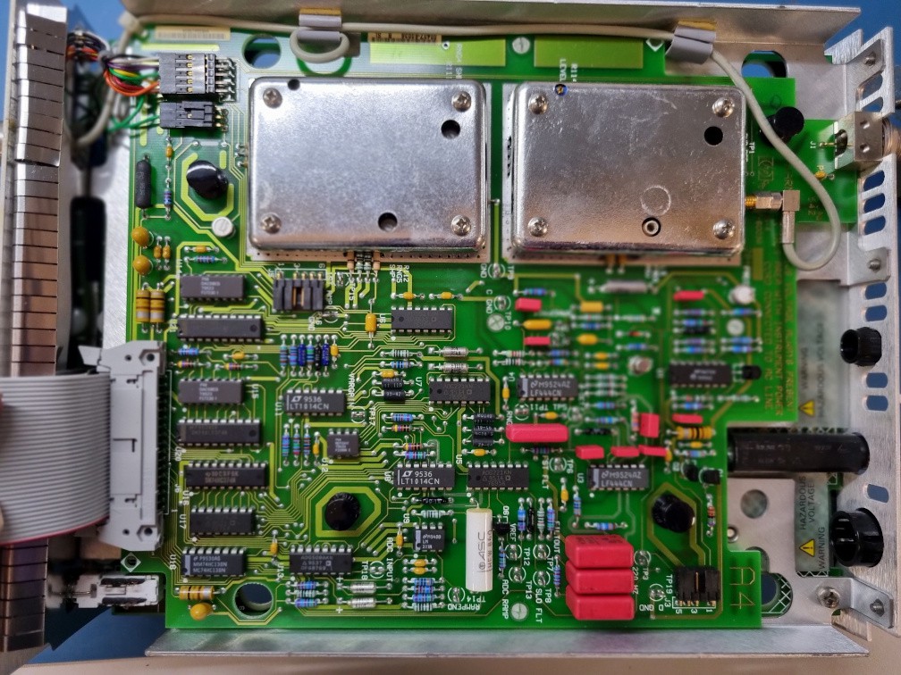
Underneath is the analogue board. The two metal cans shield the RF stuff.
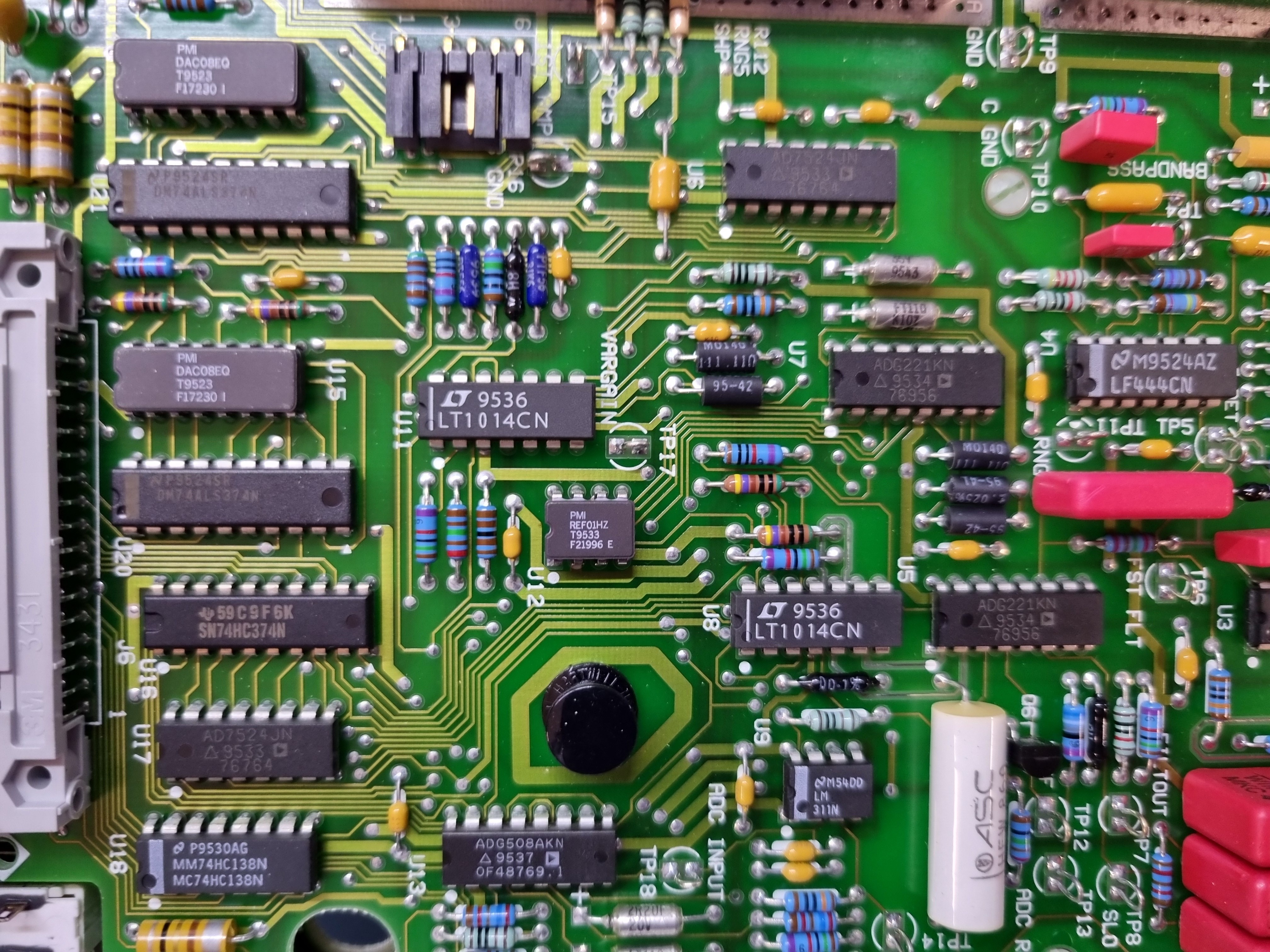
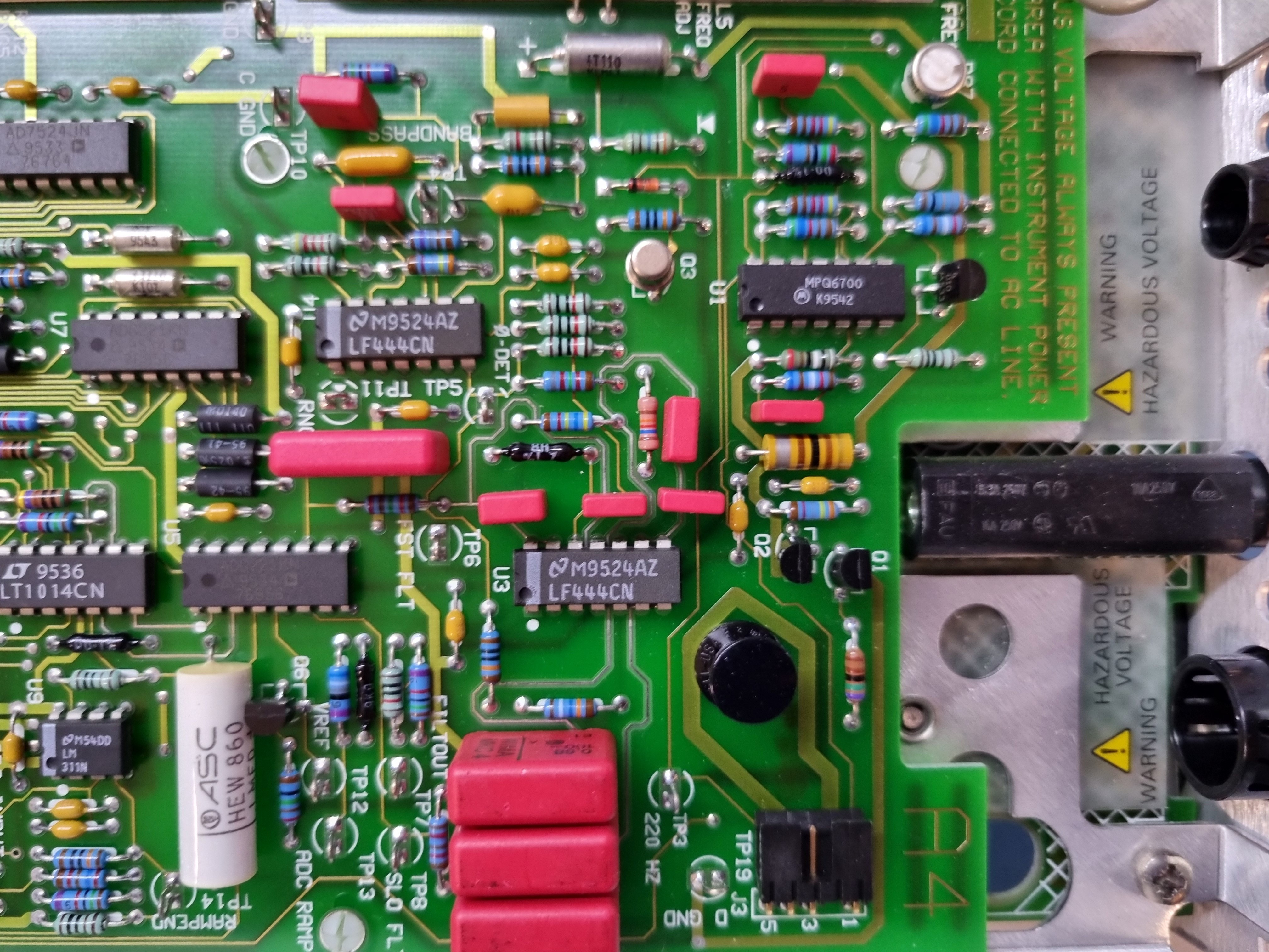
Close-up views
Discussions
Become a Hackaday.io Member
Create an account to leave a comment. Already have an account? Log In.