 Shih Wei Chieh
Manufacturing of Large Dye Sensitized Solar Cell at home from Shih Wei Chieh on Vimeo.
Introduction
Dye-sensitized solar cells (DSSCs) represent an easily manufacturable and cost-effective photovoltaic device and can be done at DIY level. However, its efficiency remains relatively low, posing challenges in meeting commercial standards, primarily due to limitations imposed by the limited conductivity of the FTO or ITO layer within the system. DSSCs offer the advantage of highly customizable patterns and colors for a transparent TiO2 layer, providing opportunities for aesthetically pleasing smart surface designs and is electrically self sufficient. Chemicals utilized in the experiment are mostly purchased from Greatcell Solar, therefore, most of the processes are conventional except the size of the cell in this experiment. The efficiency is about ~5.8V and ~51mA. The low current performance is due to the absence of the parallel circuit here.
1. Experiment
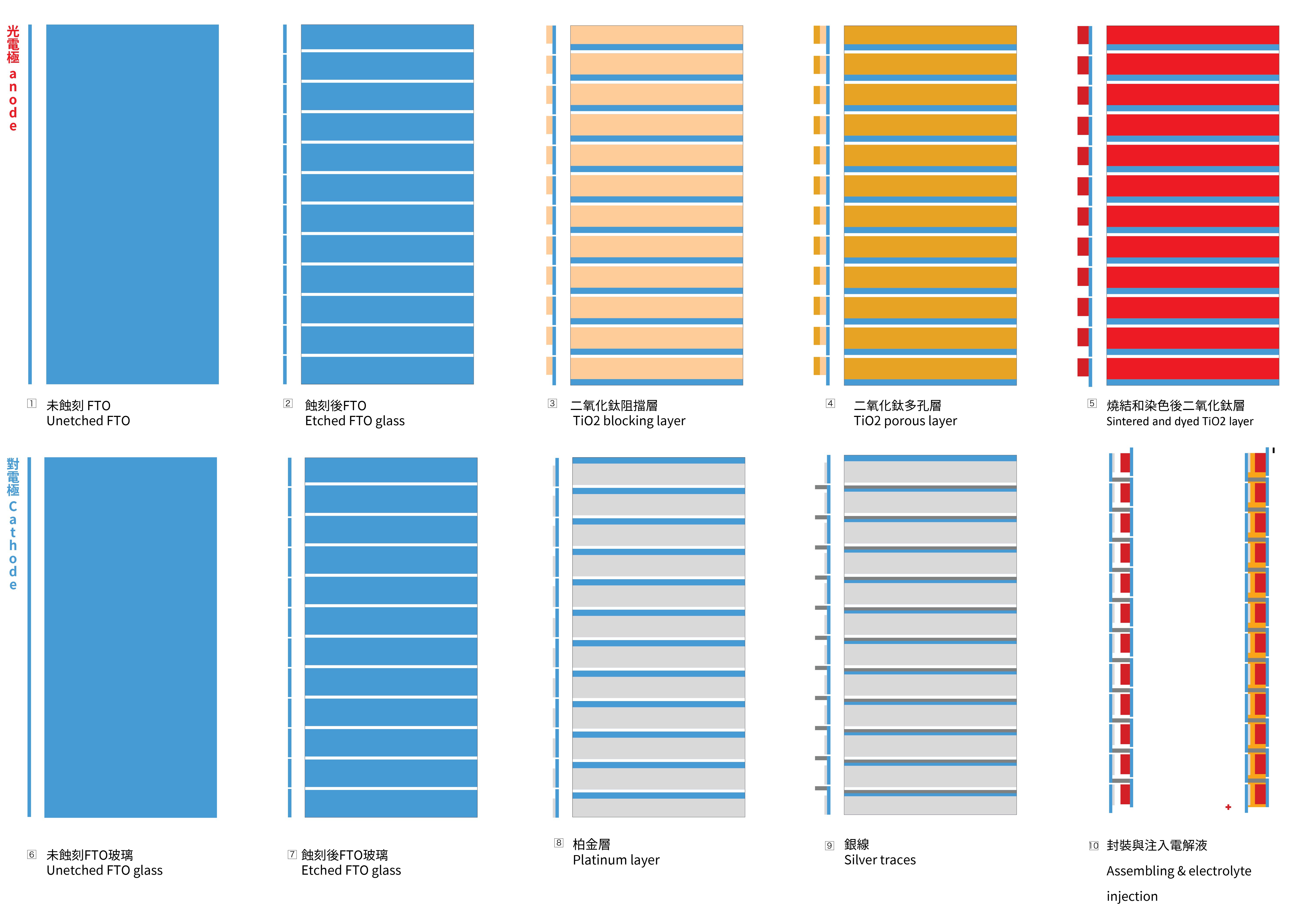
1.1 Etching the series circuit on FTO glass
To achieve the necessary voltage, a series circuit is needed to be created with the glass substrates. To achieve this goal, the FTO glass needs to be etched, to create a vertically connection between two FTO glasses. The first picture below illustrates the cross-section of the structure and the positioning of the 12 cells.
About the chemicals employed in this section, firstly, adding 26.3 mL of 38% hydrochloric acid solution to a beaker and then dilute it with water to reach a total volume of 100 mL, to make a 2M HCL solution. The wet photoresist I used here is a product LP8901V6 purchased from Great Eastern Resins Industrial Co. Ltd.(GRECO).
1.2 Sintering of the blocking TiO2 layer and porous TiO2 layer on the photo-electrode
- Apply Kapton tape to the glass to create the mask for the TiO2 layer coating.
- Apply the BL-1 paste with a glass coater. This mask will be shared to make the porous layer later.
- Place the photo-electrode in the kiln, ramping up to 125ºC at a rate of 8ºC per minute without removing the Kapton masks. Maintain this temperature for 30 minutes, and then allow it to cool naturally to room temperature.
- Take the cooled glass out and coat the glass again with with 18NR-T paste with a glass coater to make the porous TiO2 layer, then fire it with a ramp rate of 8 ºC per minute to 450ºC. Keep it at 450ºC for 30 minutes before allowing it to cool down naturally to room temperature.
1.3 The sintering of the platinum on counter-electrode
- Apply the kapton tape on the counter-electrode according to the diagram above.
- Coat the PT-1 paste purchased from Greatcell Solar with glass coater.
- Fire the glass with a ramp rate of 8 ºC per minute, reaching a temperature of 450 ºC, and is maintained at this temperature for 30 minutes. Cool the glass down to room temperature naturally.
1.4 Dye preparation
- Dissolve 0.1 g of N719 dye powder in 250 ml of 95% ethanol in a light-proof glass bottle or beaker placed in a dark environment. Consistently stir it at 50ºC with a heat stirrer for 18 hours to obtain the final N719 dye solution.
- Immerse the prepared TiO2 photo-electrode in the N719 dye solution in a shallow container for 24 hours at room temperature. Cover the container with cap or plastic wrap to prevent the evaporation of the dye solution.
- Take the dyed electrode out and rinse off any extra dye with 95% ethanol. Recycle the left over dye solution in the container by transferring it into a light-proof bottle.
1.5 Making the silver traces on the counter-electrode
- Apply Kapton tape to the glass as coating mask according to the diagram.
- Coat the 725A silver paste purchased from Acheson's on glass with a glass coater.
- Place the counter-electrode in the kiln and fire it at 120ºC for 15 minutes to cure the silver traces.
- Cool the glass down to room temperature naturally.
- Remove the tapes.
1.6 Electrolyte preparation
In this experiment, I use EL-UHSE from Greatcell Solar as the electrolyte. For the DIY version, two formulas can be followed:
- 64mg of iodine (I2), 830mg of potassium iodide (KI), and 10ml of ethylene glycol.
- 127mg of iodine crystals, 830mg of potassium iodide (KI), and 10ml of ethylene glycol.
1.7 Cell Assembling
Electrolyte should be injected between the glasses with a dropper from the edge of the glass. But due to the large size and deformation caused by the 450ºC, the injection was not so easy as working with the smaller cell. Therefore I pour the electrolyte on the center of one electrode and place another electrode on top of it afterwards. The two electrodes are fixed with coated sides facing to each other with several clips.
2. Results and obstacles
2.1 Measurement
This measurement did not take the participation of the solar simulator but only with nature sunlight at noon in Taiwan. The open circuit voltage and open circuit current are measured as 5.8V and 51mA respectively.
2.3 Assembling without DuPont Surlyn film
The assembling part in this experiment was cost-effective and temporary without Surlyn film, therefore the electrolyte and silver traces are not separated. Some of the silver traces were found corroded the day after the assembling. It was challenging to heat-press the Surlyn film with this large-size cell without proper machine.
However, despite this issue, the cell still exhibited an output of 0.33 watts under noon sunlight after one month, suggesting that there is no significant decline in performance. This may be attributed to the silver traces not being tightly bonded with the FTO, resulting in similar measurements between cells with compact and corroded silver traces. The proper method for assembling the electrodes with Surlyn film or other compounds at the DIY level is still an area that requires exploration and investigation.
3. Discussion
Certain challenges persist, including the need for precise temperature control to prevent glass deformation when dealing with large glass surfaces, which cause the difficulty to inject electrolyte afterward. Additionally, assembling techniques must be carefully implemented to prevent electrolyte leakage and corrosion of silver traces within the cell, a potential consequence of the iodine-based electrolyte. Addressing these challenges is crucial for enhancing the overall performance and sustainability of Dye-sensitized solar cells.
Reference
- Martineau, David. n.d. “Dye Solar Cells for Real.”
- Wei, Tzu‐Chien, Jo‐Lin Lan, Chi‐Chao Wan, Wen‐Chi Hsu, and Ya‐Huei Chang. 2013. “Fabrication of Grid Type Dye Sensitized Solar Modules with 7% Conversion Efficiency by Utilizing Commercially Available Materials.” Progress in Photovoltaics: Research and Applications 21 (8): 1625–33. https://doi.org/10.1002/pip.2252
- Mariani, Paolo, Antonio Agresti, Luigi Vesce, Sara Pescetelli, Alessandro Lorenzo Palma, Flavia Tomarchio, Panagiotis Karagiannidis, Andrea C. Ferrari, and Aldo Di Carlo. 2021. “Graphene-Based Interconnects for Stable Dye-Sensitized Solar Modules.” ACS Applied Energy Materials 4 (1): 98–110. https://doi.org/10.1021/acsaem.0c01960.
- https://www.ossila.com/products/fto-glass-unpatterned#FTO-Glass-Etch
- Make a Solar Cell - TiO2/Raspberry based. https://www.youtube.com/watch?v=WHTbw5jy6qU
- “From Capitalist Realism to a Solarpunk Reality: Building the Infrastructures of a Better Future - YouTube.” n.d. Accessed February 9, 2024. https://www.youtube.com/watch?v=rsu8hHtomtQ.