 ELECTRONOOBS
READ THIS:
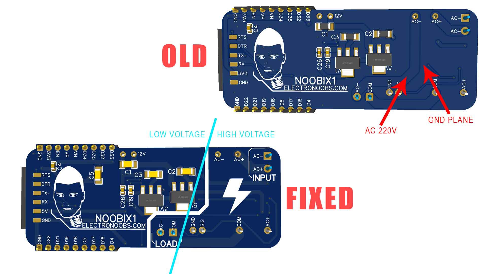
● Some of you guys on the community commented that the AC high voltage clearance is too low. YES, YOU ARE RIGHT! I usuall add copper plane to all my PCBs and that was a mistake made ina hurry. So even if you see a bad clearance in the video, the final PCB you can download from below, has all the errors fixed with enough clearance. For a 1.6mm thick OPCB, the recomended clearance on the same layer for 220VAC is 2.5mm or above. Now all the high voltage is separated on one side with decent clearance.
● Other mentioned parts were about the connectors that they can't handle more than 150V and 6A. Actuall, the connectors I've used were rated for 300VAC and 10A but maybe the supplier is a liar so I can't know for sure. Also, the maximum current I say in the vidoe thos PCB is rated for is 2A. That's because the SSR could only handle that so we would never get to above 6A. If you do that, is your mistake!
● You also mentioned that the exposed tracks and pads are dangerous to handle! Whaaaaat? Why would you handle such a PCB while connected to voltage? To use such PCB, you should first cut off power from your entire house by lowering the safety switches. Then connect the PCB to power and load. Then place the PCB inside of an insulated plastic case. And then you turn the power back ON. You should never touch the exposed PCB, are you crazy? I say that in the video. A lot of other commercial IOT PCBs have exposed pads/trackas but you should never touch them!
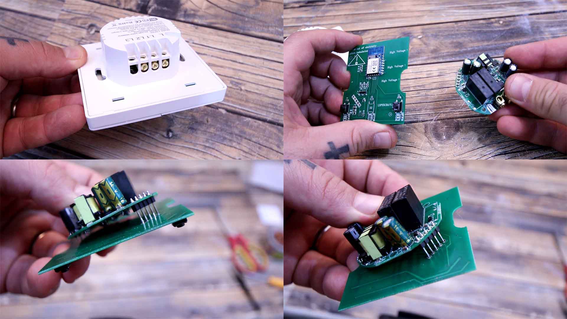
Another thing that was mentioned was the voltage regulator module. The module is ok because it has an insulated connection through a transformer so that’s not a problem. But yes, the module has high voltage and is soldered a bit too close to the PCB (actually it has around 2mm of clearance which sould be ok). For that we have two options: Add a plastic separator in between the module and the PCB, or maybe just solder the module in mid-air. For example this below is an IOT board that I bought and works with Alexa (is a commercial PCB). This has the regulator module here and the IOT circuit on the other side on another PCB. They are merge together with some pins of a few mm to add insulation. I could do the same with my PCB and like that we have enough clearance. So, problem solved.
So for those who are exaggerating and saying that this will kill people and insulting me!!! Please tell me how? The only way to kill someone here is if you touch the PCB while powered on. And you should never do that. And that applies to so many other PCBs. You should never touch a powered relay, it has exposed pads. Never touch a power supply neither. Never touch a converter and so on. These are all dangerous to touch if powered on.
The only thing I could imagine that could happen before I’ve fixed the clearance, is that the high voltage could have jumped to the low voltage blowing up your microcontroller. And since the tracks are 0.22mm they would acts as fuse and just burn out. So my only concern was related to fire and not being electrocuted. But even so, if you were right there are ways to tell me that. That’s why I want to talk about constructive comments. If you see an error in my videos, you don’t have to call me names. You can just say which is the error and if you can, you could even say a solution to that error. That’s constructive and it will improve the project and help the community. Saying that I’m a s***id f**k and should delete my channel, is not constructive!!
Discussions
Become a Hackaday.io Member
Create an account to leave a comment. Already have an account? Log In.