Close
0%
0%

25in24 Electronics Project Board

Re-vitalizing and modernizing a Radio Shack 65in1 kit for educational purposes - my DesignLab Residency!

Similar projects worth following
In the early 70's Radio Shack sold different educational kits so you could learn about electronics without taking a formal class. The 65in1 kit allowed the experimenter to put together 65 different experiments without any extra supplies. All of the circuits were wired using spring connectors and pre-stripped wires, and included excellent documentation. This kit started my journey on becoming a hobbyist, Electrical Engineer, designer and educator. My goal with this project is to produce a low cost, low entry level way for students to learn about electronics without the need of extra tools and supplies. Additionally, I am hoping to create well documented experiments so anyone can learn the basic concepts of electronic hardware. The name 25in24 pays homage to the original name - starting with 25 experiments while fast forwarding to the year 2024!

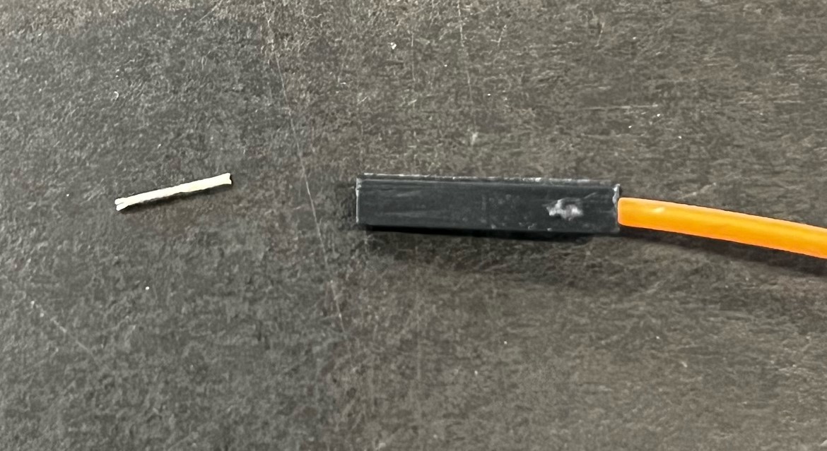
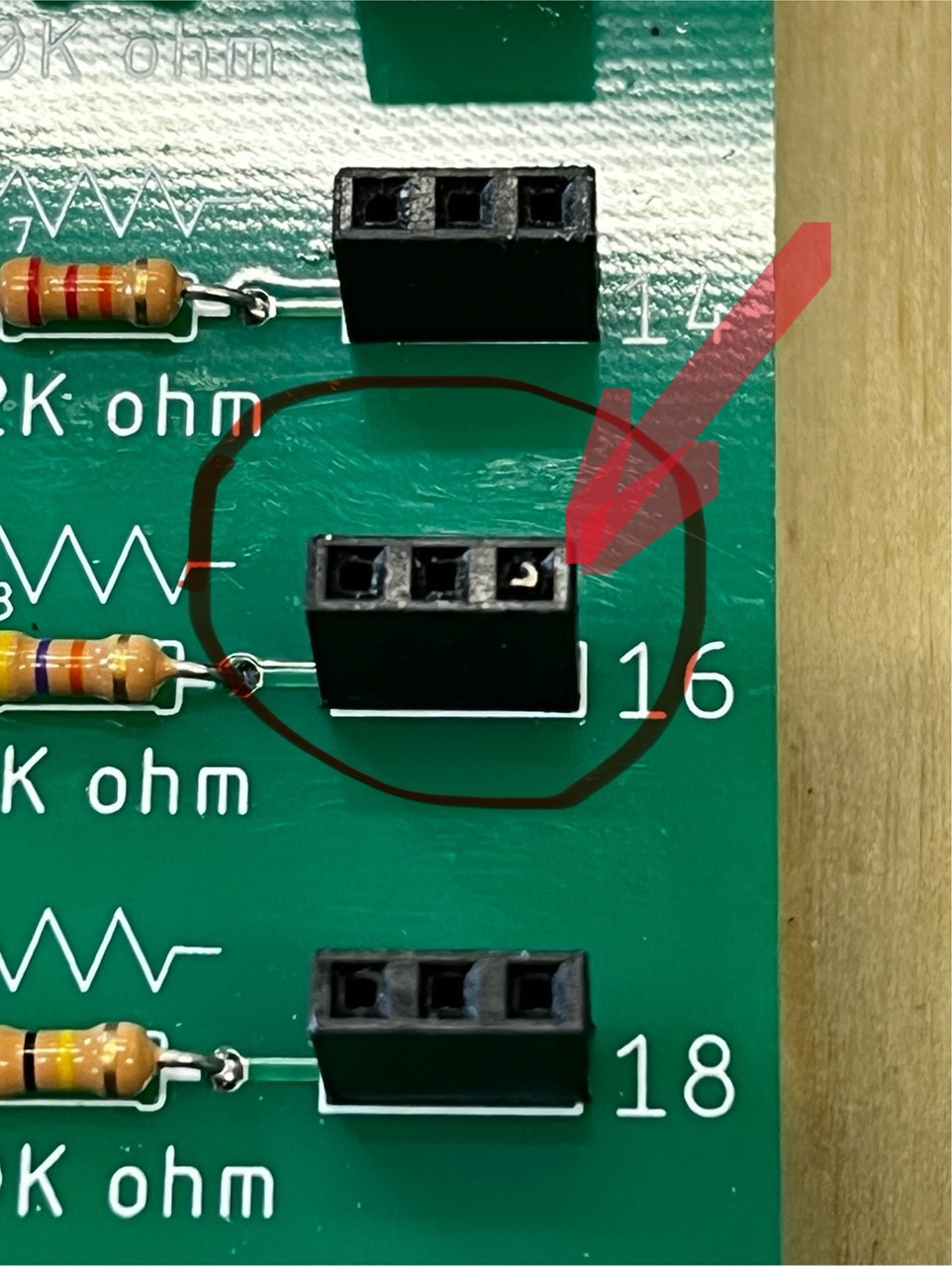
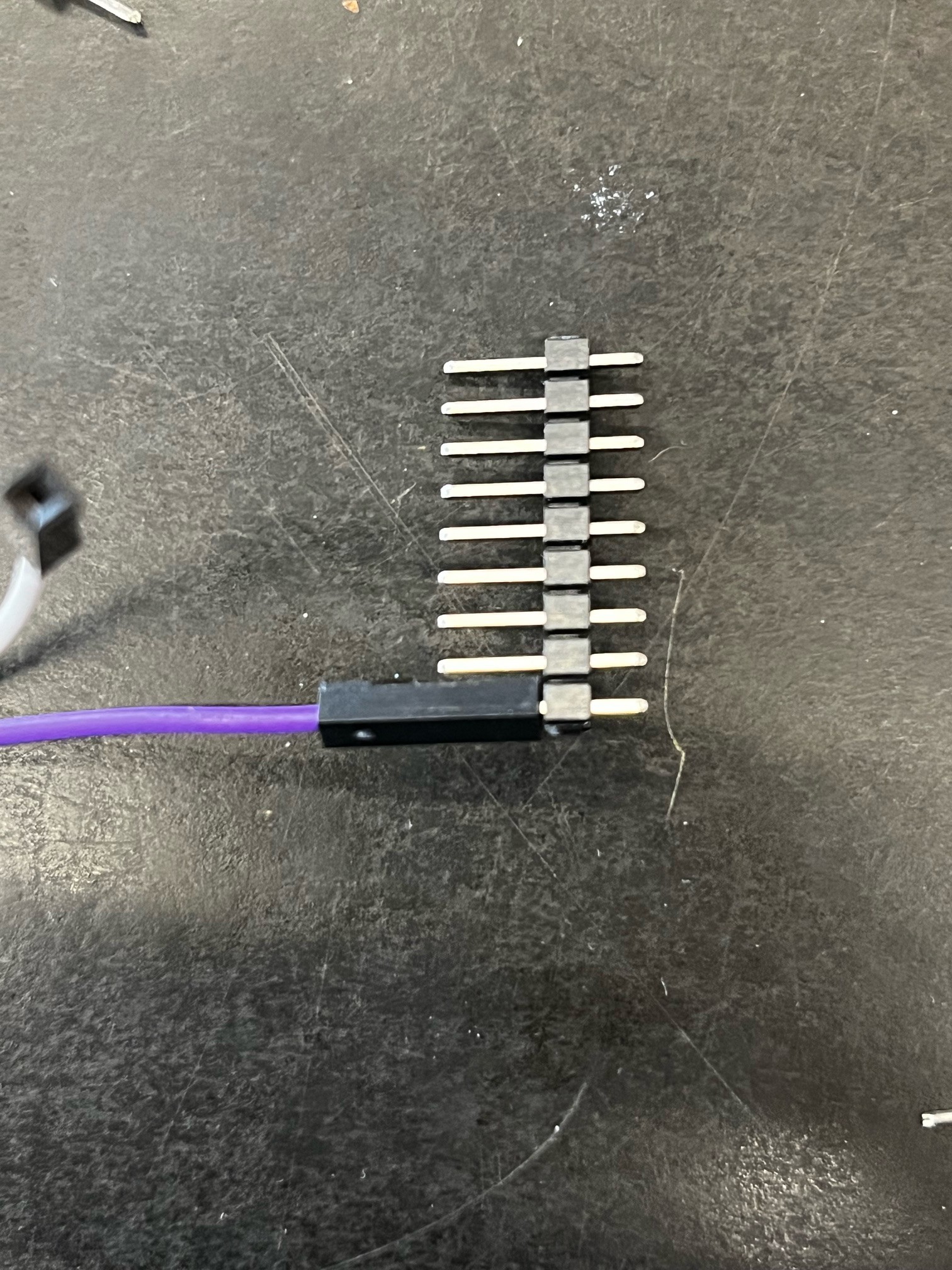
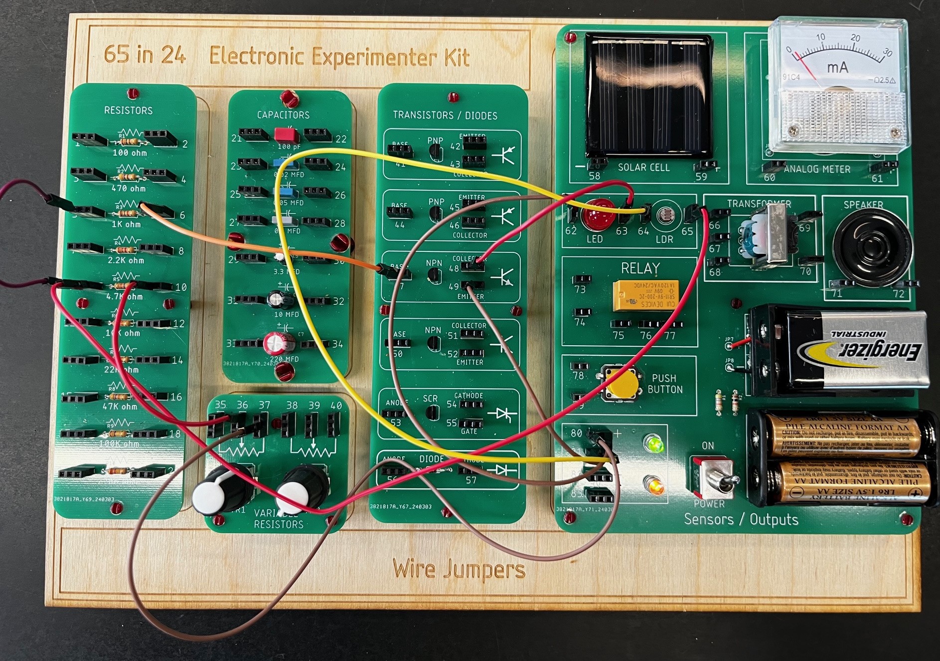
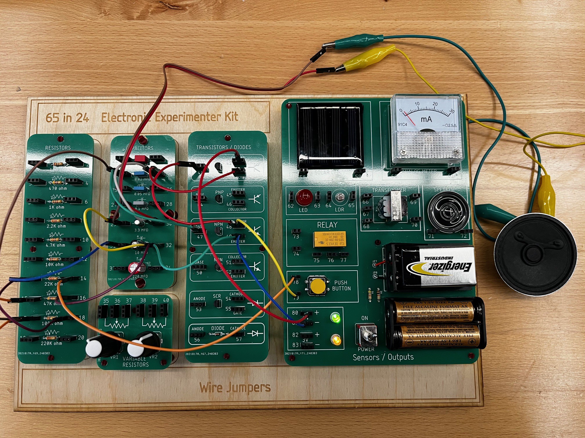
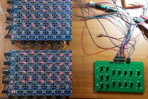
Phase 1:  My goal is to design five PCBs that include resistors, capacitors, active devices and various input and output components.  These will mount on a laser cut wood base similar to the original design, but smaller.  One of the issues with the original design is the springs would oxidize, and the wires would break.  I am planning on using standard breadboard jumper wires with headers on the board to make the connections.  

  • Week 6 - Final project testing / PCB design

    Tom Thoen04/04/2024 at 23:02 0 comments

    Finally tested the last projects. 

    Revised the Sensors / Outputs PCB - using 3 pin headers to transition to SMT so they don't all have to be soldered manually.  Here is the final layout:

    My next plan is to solder up 3-4 of these boards and have people test them out for functionality / look / feel.

  • Week 5B - Next steps

    Tom Thoen03/28/2024 at 23:05 0 comments

    Next steps:

    • I still have a number of projects to test - documentation is going to be the biggest time challenge.
    • Modifications for the Sensors / Outputs board - need to spin up a new PCB.
    • Once everything is working create a BOM / PCB files / some kind of basic instruction document.  Ultimately this will be a big task to replicate the original manual from Radio Shack, which was very good!
    • Finalize design of overall box - most likely laser cut from wood.
    • Start Phase 2 - Digital logic circuits!

  • Week 5 - more testing!!!

    Tom Thoen03/26/2024 at 18:31 0 comments

    So far I've been able to get about 8 experiments working.  

    Lessons learned:

    The wire jumper ends break fairly easily, especially when I "rip" them all out of the board (memories of 5th grade!).  This also often leaves the pin stuck in the female header.  Also, the typical Dupont wire jumper pins are a bit small for the female sockets - they are a bit loose and don't make reliable connections and pop out of the sockets easily.  I did this originally to keep the sharp pins off the board, but now the plan is to replace the female sockets on the board with male .025" header pins.  The female to female jumper wires are much more secure on the header pins and the typical header pins I use are pretty robust.  Plus, they won't break!

    Maybe you think I'm overthinking this, but if this part of the board doesn't hold up, it will be very frustrating to the user!

    As there are a few other changes I'll be making I'll spin up another rev on the PCB designs.  The speaker sounds tinny as it's so small, so I'll probably replace the Solar cell real estate with a larger speaker...

  • Week 4 - Project testing

    Tom Thoen03/19/2024 at 23:16 0 comments

    Mixed success this week - I was able to get two projects working; however several others did not work.  Not sure if the issue is difference in components or not.  At this point I'll probably work on circuits *based* on the original projects but tweaked to work with my new hardware. 

    Project examples (need to create YouTube videos... :-o )

    Light meter:

    Siren:

    (Note that original speaker on PCB is pretty small and not very loud!!

  • Week 3 part 2 - testing

    Tom Thoen03/14/2024 at 23:14 0 comments

    Well, initial testing was more difficult than expected - took about five hours just to get a couple of basic circuits working.  Made a number of incorrect assumptions / mistakes including:

    • Assuming it might be differences between components (germanium vs. Silcon, transformer winding ratio, meter current)
    • Blaming the jumper wires (a bit old and janky)
    • Rushing too much when making the circuits

    Finally found out my resistor board PCB traces had not been routed 100%.  Yikes!  After re-soldering the board a couple of the projects are finally working.  Next step is to get a number of them fully tested and documented...

    Project # 1 test - tone generator :-)

  • Week 3 - PCBs in, soldering and assembly

    Tom Thoen03/12/2024 at 23:02 0 comments

    PCBs came in!  Thanks JLCPCB!!

    Soldered up the boards - Kino in the Design Lab Laser cut a cool outline in plywood that I'm using for the base for testing.

    Boards were soldered and mounted.  There were some clearance issues with the meter so some extra drilling needed to be done!

    I'm very happy with the layout - Later this week I will be working on testing using some of the original 65in1 experiments.

  • Week 1 & 2 - PCB Layouts

    Tom Thoen03/05/2024 at 21:50 0 comments

    I've started by laying out the five boards in Eagle 9.52.  Boards are now being ordered through JLC.  All parts have been ordered through Mouser and Digikey - however sourcing a small meter and solar panel that will match have been a bit of a challenge, as there are no specs published.

    I also did a layout of all the boards to make a laser-cut base out of wood.  Ultimately it will also have a box to hold the jumper wires.

    Once all boards and parts are in I'll begin assembly!

View all 7 project logs

Enjoy this project?

Share

Discussions

Doug LaRue wrote 03/26/2024 at 02:47 point

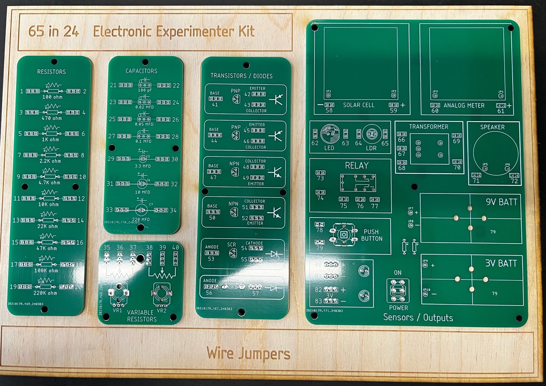
Not sure if the original kit had plans for making a Volt meter but for teaching circuits and Ohm's Law, voltage and current meters are important tools to have. So besides making circuits, having enough components to make the play circuits AND have a volt meter wired up for the learner can explore the circuit would be great.

I was also thinking it would be handy having the xformer ratio listed under the part and maybe a "Power Sources" label added to the 9v and 3V outputs. Would also like to see the relay diagram but would be tough to fit that in the space. Hopefully it's on the side of the part.

  Are you sure? yes | no

Tom Thoen wrote 03/26/2024 at 17:26 point

Doug - great suggestions!  The original did have a current meter - I'm planning on having a couple of experiments with series / parallel circuits, etc where they can use the meter.  I'll definitely add the Power Sources label and turns ratio on Txformer.  I'll probably have enough room for the relay diagram too like the original.  Silkscreen layout seems to always takes more time than the original component layouts!! :-)

  Are you sure? yes | no

JammerX19 wrote 03/25/2024 at 16:46 point

I would love to buy this kit and use it as a build night activity for our ham radio club. 

  Are you sure? yes | no

Tom Thoen wrote 03/25/2024 at 17:48 point

Once I get everything finalized I'll post the build files.  However I'm also open to selling kits at some point - will let you know!

  Are you sure? yes | no

Doug LaRue wrote 03/25/2024 at 16:03 point

This kit is fantastic and as with others, brings me down memory lane as I had the 100:1 kit.

Currently trying to teach Middle School kids basic circuits and Ohm's Law using alligator clip leads and resistors and now starting a soldering lesson. Would be great to go in reverse on a kit like you have here. ie teach soldering first, make the kits and then use them to learn circuits! I like it better than the $50 Arduino Super Starter Kits I've used for small groups. Nice work.

  Are you sure? yes | no

Tom Thoen wrote 03/25/2024 at 17:50 point

Thanks!  Yes, that was my thought too - the soldering would be pretty basic - large scale pitch / through hole components would be an easy soldering project.  I also agree with the starter kits - the price point is good, but working with traditional breadboards is tough for younger kids.  

  Are you sure? yes | no

Doug LaRue wrote 03/25/2024 at 21:15 point

I love the breadboard kits but when teaching circuits and following electrical paths things get lost. Not to mention dealing with inserting components correctly and getting the jumper wires into the correct row. Gotta have a good grasp of a circuit and the way you did it, as did the springs, is ideal for the beginner. CS is starting to become a HS requirement and I would love to see basic electrical circuits be part of that.  I'll keep an eye out for your build files and thanks for sharing.

  Are you sure? yes | no

Robb Smith wrote 03/13/2024 at 04:28 point

Wonderful!  Seeing this is like bumping into a long-lost friend on the street.  Now all I need to be truly happy is a few Tab books; I read and re-read my copy of "Build Your Own Working Robot" till the book fell apart.

  Are you sure? yes | no

Tom Thoen wrote 03/13/2024 at 05:09 point

Glad it resonates with you! I feel like I grew up in a magical time as an electronics hobbyist. So glad there are websites out there that still have copies of magazines, catalogs, etc. I read BYOWR so many times - I think I still have my original copy!

  Are you sure? yes | no

Dan Maloney wrote 03/14/2024 at 16:27 point

I had that book too!

  Are you sure? yes | no

[deleted]

[this comment has been deleted]

Dan Maloney wrote 03/07/2024 at 04:17 point

Looked this up in the 1976 Radio Shack catalog -- $21.95. That must have been a fortune to my parents back then -- equivalent to $119 today! Wow!

Page 92 if you're interested: https://www.radioshackcatalogs.com/flipbook/1976_radioshack_catalog.html

  Are you sure? yes | no

Tom Thoen wrote 03/07/2024 at 19:45 point

Wow, that catalog was a trip down memory lane!  So many memories of things I could never afford when I was a kid.  The price on my 65in1 was $17.95 - makes me appreciate my Dad's willingness to help me get into electronics!

And one of the main goals of this project is to make something similar with a low cost point so they can be used in homes / classrooms, etc. without spending a lot of money...

  Are you sure? yes | no

Dan Maloney wrote 03/06/2024 at 17:23 point

Pretty sure this 65-in-1 is the exact one my parents got me for Christmas when I was about 11 or maybe 12. I hadn't really thought much about electronics before that, but I was on fire for the field after building that first circuit. That one present kicked off this whole crazy journey. Thanks Mom and Dad!

Thanks for the memories. Looking forward to seeing where this project goes!

  Are you sure? yes | no

Tom Thoen wrote 03/08/2024 at 15:14 point

I think this was about the same age I got mine too!  I found this one on eBay to show other friends / students how I started my path on learning about Electronics.  I miss these days of P-box kits and buying parts at Radio Shack.  My Dad also payed for my subscriptions to Popular Electronics and Elementary Electronics, which also had a huge impact on my journey too.  Looking forward to developing and sharing the project!  Cheers!

  Are you sure? yes | no

Similar Projects

Does this project spark your interest?

Become a member to follow this project and never miss any updates