So far I have described how the camera can be used standalone, using the shutter release button to take a photo. A feature of the previous model was serving a web page to allow pictures to be taken and stored photos to be reviewed. I have done something similar here. In the last log entry I mentioned the combined Wifi/Bluetooth USB adapter. This particular model is able to act as a client and station (AP) at the same time. In the video below, I start by pinging an IP on my home WLAN (192,168.1.3). As the Pi boots, it first gets the camera running (indicated by the green light), then connects to the WiFi. This can be seen when the camera starts returning a ping.
After this I scan for available wireless networks, one called 'Camera' is found. At this point I could connect directly to this network and access the web interface at 192.168.0.1 as if I was out and about and using the camera away from home WiFi. For demonstration purposes, I'm going to continue and access the interface at 192.168.1.3
The interface is very simple and consists of four buttons along the top:
- Download - view full size version of the picture. Only thumbnails are shown in the gallery for speed
- Take Photo - self explanatory
- Delete - delete the photo currently shown
- Print - I'll get to this in a minute
The interface is using the lightweight library from http://fotorama.io/ with a few jquery bits for the buttons. I'll hopefully get around to making the source available when I get on to the software write up later on.
Selfie Button
One feature I wanted was to be able to take a group selfie with remote shutter release. I had lots of ideas around this, a few of which are shown below
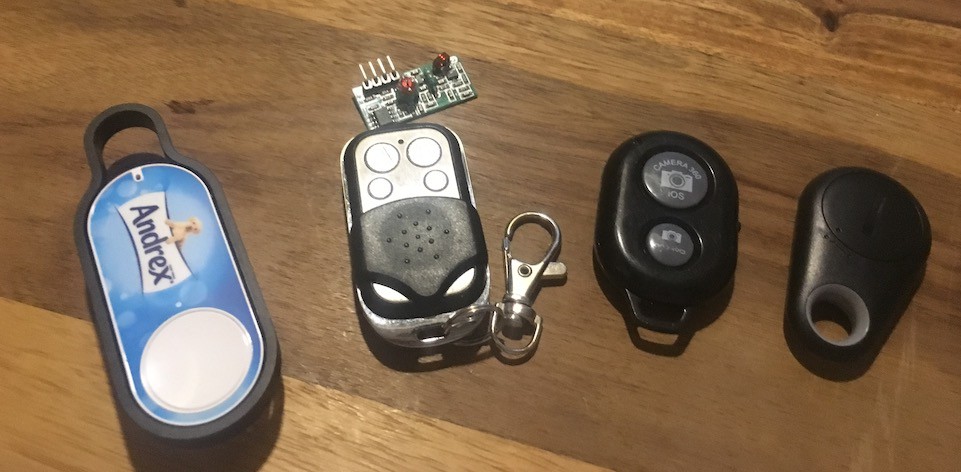
- Amazon Dash Button - It works. It's quite straight forward to detect when this connects to the camera's wifi but a bit slow and takes a while to reset and be ready to trigger the next photo.
- 433MHz Keyfob and receiver - again, it works but range not great and requires an extra piece of hardware squeezing in to the camera.
- Cheap Selfie Shutter - This works over Bluetooth and presents itself as a HID Keyboard. It works fine when right next to the camera but when it is on the edge of it's range (which is only about 2 metres in this setup), it starts to act erratically taking multiple seconds to send the command, repeating commands. Good when it works but not reliable.
- Another cheap Bluetooth button - Not sure what this is or how it works as I've only just acquired it. Only cost 99p so not expecting much, but we'll see.
I also considered an Infrared receiver but I would have to find somewhere for it and I'd already completed the wiring to the camera module and indicator/flash panel which would seem the obvious place for it.
So, I went the DIY route!
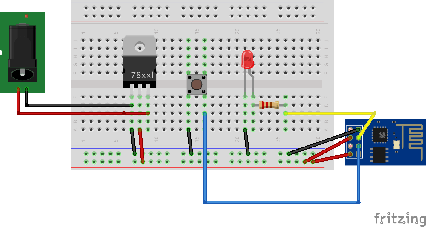
The Dash button was the most reliable and had the best range but was unsuitable because of the lag and the delay on repeated button presses. I'd used ESP8266 WiFi modules before so had a few lying around and thought they might be suitable. All that is required is to connect to an AP and call the URL http://192.168.0.1/takephoto.php when a button is pressed - easy!
I was going to use the ESP01 module due to it's cheapness and smallness. I wired it up as below, loaded the code on to it using the Arduino IDE and it worked like a charm!
#include <ESP8266WiFi.h>
#include <ESP8266HTTPClient.h>
HTTPClient http;
void send_event(const char *event);
// Wifi setup
const char *ssid = "YOUR_SSID";
const char *password = "YOUR_PASSWORD";
// Hardware setup
const int buttonPin = 0; // the number of the pushbutton pin
const int ledPin = 2; // the number of the LED pin
// Variables will change:
int buttonState; // the current reading from the input pin
int lastButtonState = LOW; // the previous reading from the input pin
// the following variables are long's because the time, measured in miliseconds,
// will quickly become a bigger number than can be stored in an int.
long lastDebounceTime = 0; // the last time the output pin was toggled
long debounceDelay = 50; // the debounce time; increase if the output flickers
void setup()
{
// Set your pin modes
pinMode(buttonPin, INPUT_PULLUP); //enable internal pullup resistor so we don't have to provide our own
pinMode(ledPin, OUTPUT);
// Bring up the serial for a bit of debugging
Serial.begin(115200);
delay(10);
// We start by connecting to a WiFi network
Serial.println();
Serial.println();
Serial.print("Connecting to ");
Serial.println(ssid);
WiFi.mode(WIFI_STA);
WiFi.begin(ssid, password);
// Wait for the connection, flashing the LED while we wait
int led = HIGH;
while (WiFi.status() != WL_CONNECTED) {
delay(200);
digitalWrite(ledPin, led);
led = !led;
}
digitalWrite(ledPin, LOW);
Serial.println("");
Serial.println("WiFi connected");
Serial.println("IP address: ");
Serial.println(WiFi.localIP());
}
void loop()
{
// read the state of the switch into a local variable:
int reading = digitalRead(buttonPin);
// check to see if you just pressed the button
// (i.e. the input went from LOW to HIGH), and you've waited
// long enough since the last press to ignore any noise:
// If the switch changed, due to noise or pressing:
if (reading != lastButtonState) {
// reset the debouncing timer
lastDebounceTime = millis();
}
if ((millis() - lastDebounceTime) > debounceDelay)
{
// whatever the reading is at, it's been there for longer
// than the debounce delay, so take it as the actual current state:
// if the button state has changed:
if (reading != buttonState)
{
Serial.print("Button now ");
Serial.println(HIGH == reading ? "HIGH" : "LOW");
buttonState = reading;
// When the button is in the LOW state (pulled high) the button
// has been pressed so send the event.
if (buttonState == LOW) {
send_event("button_pressed");
}
}
}
// save the reading. Next time through the loop,
// it'll be the lastButtonState:
lastButtonState = reading;
}
void send_event(const char *event)
{
// set the LED on whle we are sending the event
digitalWrite(ledPin, HIGH);
if(WiFi.status()== WL_CONNECTED){ //Check WiFi connection status
// Make a HTTP request
http.begin("http://192.168.0.1/takephoto.php");
http.addHeader("Host", "raspberrypi:8080");
http.addHeader("Content-Type", "text/plain");
int httpCode = http.GET();
String payload = http.getString();
Serial.println(httpCode); //Print HTTP return code
Serial.println(payload); //Print request response payload
http.end();
}
// Finished sending the message, turn off the LED
digitalWrite(ledPin, LOW);
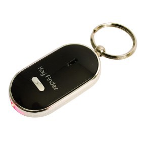
}I then had to build it into an enclosure. After a bit of searching, a 'locate your keys with a whistle' device seemed like it might fit the bill.
I opened it up and removed all the support structure to leave just the bare shell
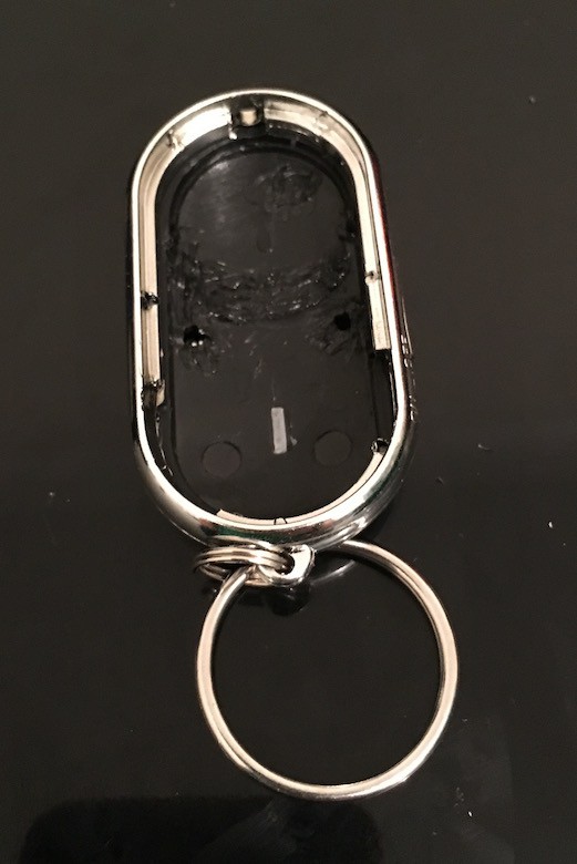
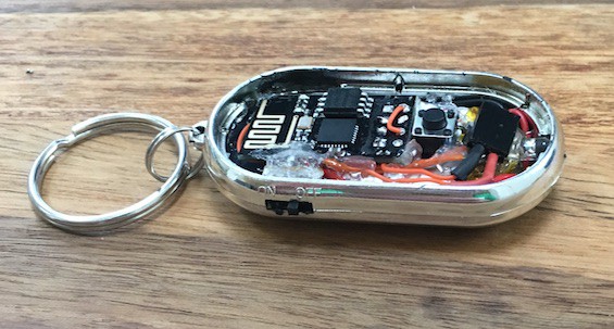
I removed the switch, LED and button from the original circuit board, then used them along with a 200mAh battery that I scavenged from a promotional video Christmas Card to build the circuit I prototyped within the body of the keyfob.
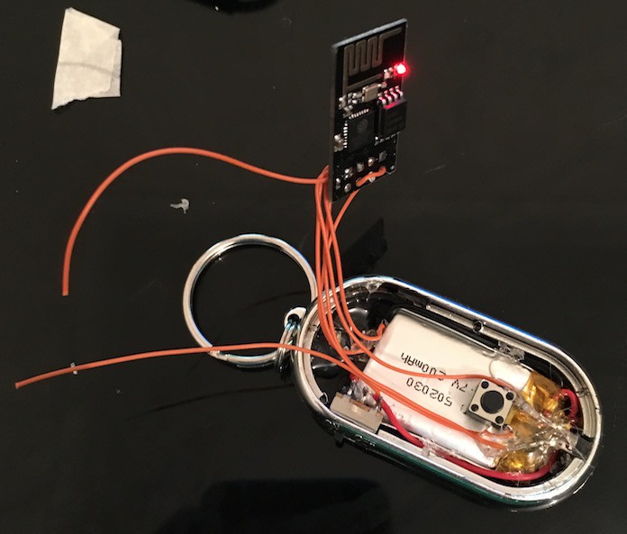
The 2 wires not attached to anything are for charging the battery. When the switch is off, the ESP is disconnected and the battery can be charged.
The 3.3v regulator is in the recess on the left and the led is back in the original position on the right.
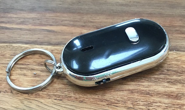
The finished article:
The Printer
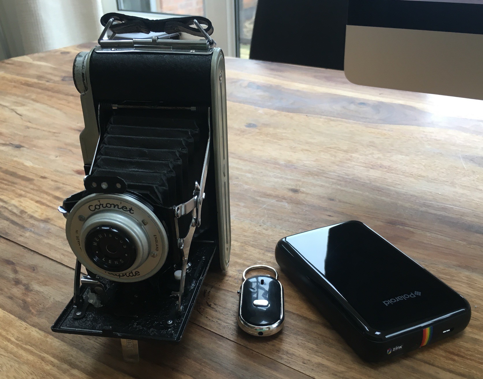
One of the features I wanted out of the camera was to be able to print the photos while on the move. This was, obviously, the best feature of the Polaroid and one that I missed with the Box Brownie set up.
There are not many options for mobile photo printing and the obvious choice seemed to be one of the little printers that use the Zink printing technology. There are a few of these LG and HP make one but I went for the Polaroid Zip as it was the same price as the others but I had read about someone being able to print to it from the linux command line.
This turned out to be true. Using a tool called ussp-push I am able to send images to the printer and get them in my hand a minute later.
Discussions
Become a Hackaday.io Member
Create an account to leave a comment. Already have an account? Log In.