 Timescale
The last couple of days I have been focussing on the console and the power and data infrastructure. With all the feature creep of late, It has become quite necessary to have a good idea what the component placements wants to be and there is a lot of wiring going on there.
The whole system is distributed 12V from the middle of the vehicle. This power goes to the front and back attached to bus bars. The RPi gets it's own 12v to 5 volt converter because of the power requirements while the rest will either power components directly or via the relay which is mainly used for 12v components, but it is very much possible to dedicate a couple of terminals to 5 volt. Many wire come in and out and even more stay within the console. In order no to have cable spaghetti, a good plan is needed.
The where and the how principles remain the same here. Mounting components much to robust, light, easy to remove or move around and result in the most efficient cable routing. More then one function!
for mounting the individual parts, i am going to make foam boxes that the components fit in snugly. Here is a test bracket for an Arduino UNO, glued and shaped to take the PCB with a tight fit :

Here a standard UNO is fitted. Without effort, it won't pop out and the foam also acts as a shock absorber.


The foam is cheap foam mats, cut, glued and shaped. But how to attack it to the main base of the console?
The answer is simple, Velcro! There will be a matrix of Velcro strips on the base and each module has Velcro on the bottom. this was, fiddling around with placement is simple.
Speaking about placement. for some reference points I also started drawing up some models based on what is connected to what and going where. Here are two examples of how the console could look:s
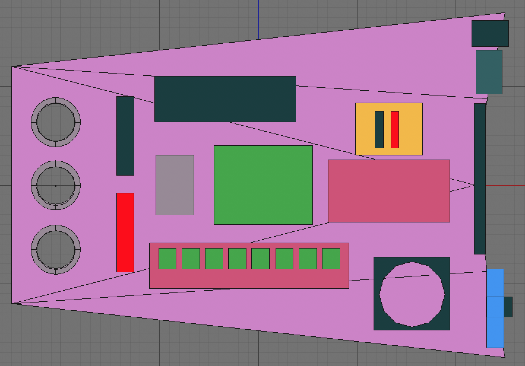
Basically I placed everything around either the RPi or the Arduino Mega. It is very data centric and does not take into regard what goes out and what stays in. So the following iteration looked like this :

As you can see, this setup is far more "hub" driven with most of the power having a clear line of side to the outside. Inside components that connect data wires are in the front.
Now there will be exceptions to every design goal, but the main goal is to have wire routing as efficient as possible. Seeing there are a myriad of possibilities, this is a problem I'd very much like user input on. these are the components in the console:
- 8 channel 12 volt relay board
- 12v bus bar
-GND 12v bus bar- 12v Powered USB hub (connected to RPi)
- 12v to 5v 3A converter for RPi
- 12v cooling fan
- Arduino mega with GPS shield (antenna goes external)
- breakout PCB with 5v bus bars and sensor connectors (Temp,hum,light, hall effect0
- Rpi4 (the brains)
- 2x 16 matrix display
- 2 axis 1 button analogue joyPad
- iPad mini (just needs power from hub)
- Break out USB
- 12v lighter socket
- potentially a 12V main switch.
Any suggestion is welcome, so please have at it1
Discussions
Become a Hackaday.io Member
Create an account to leave a comment. Already have an account? Log In.