 Davide
Introduction
In today's world, gaining control over energy consumption is a top priority. There are two main methods for monitoring domestic energy use:
1. Current Phase Measurement using a Clamp Meter. This method utilizes clamps that attach around a single conductor to measure current flow. It's a non-intrusive approach, meaning it doesn't require interrupting the power supply.
2. In-Line Meters: These meters are installed directly into the electrical circuit, interrupting one or more phases to measure current. While effective, they require professional installation and can be less scalable for multiple circuits.
Both methods often offer an interface with a pulse output, where the pulse frequency is directly proportional to the real-time energy consumption. This allows for easy data collection and analysis.
This project provides a solution for collecting pulses from multiple meters and sending them to a database for further analysis. Additionally, since pulse outputs are also used by other types of metering systems (gas, water, etc.), this system can be easily expanded to support them.
The project
The core of the project is an ESP32-S3 microcontroller, which receives and collects pulse data from meters. After a quick online search, I couldn't find much info on the type of pulse the meters output. So, since I wasn't sure, I did some tests with an oscilloscope and a load (a hair dryer) to generate the pulses. ( however this awesome project helped me a lot openenergymonitor )
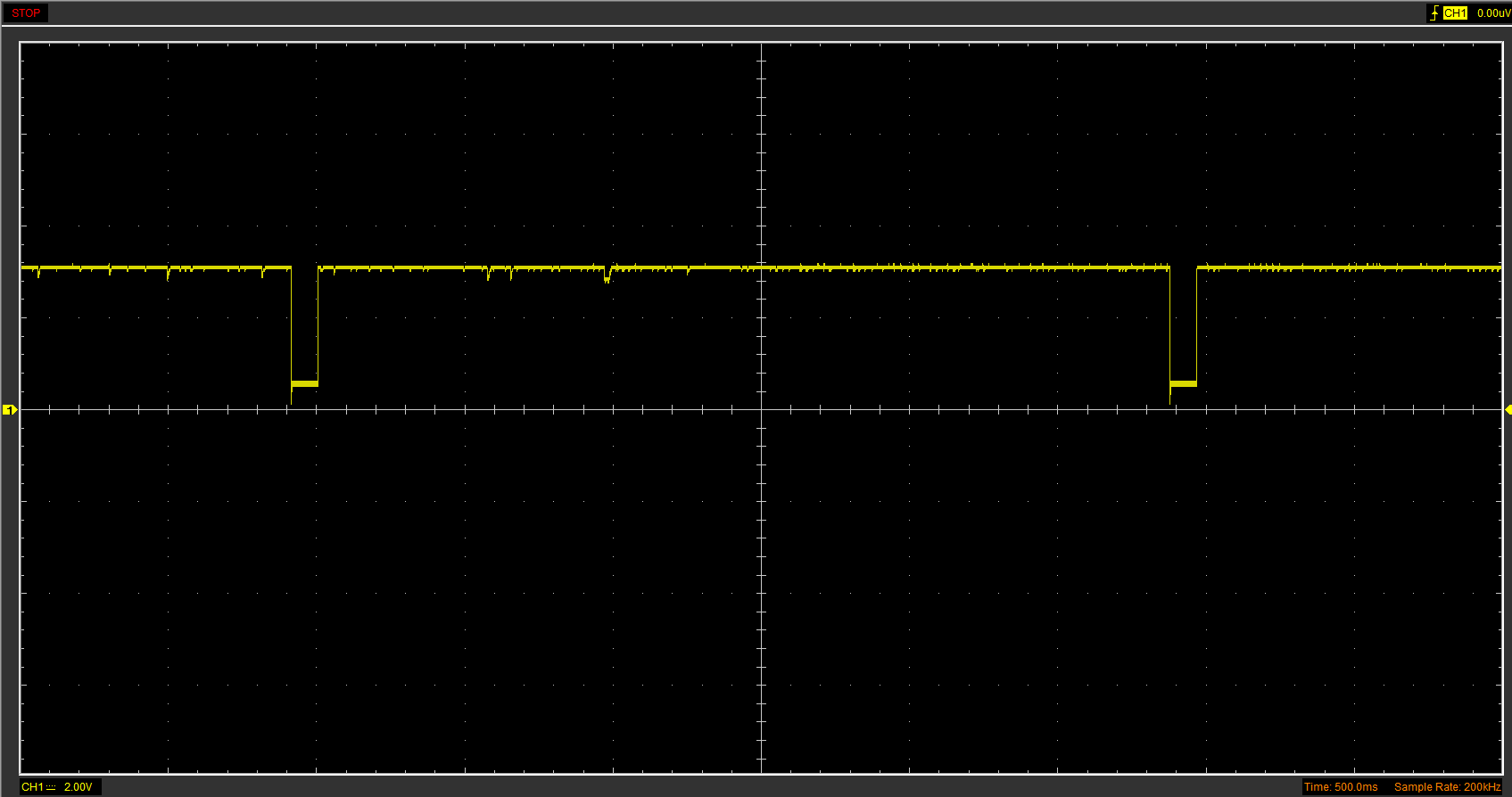
Using an oscilloscope connected to the meter, background noise can be seen when the output is not active (floating output), while a short circuit can be observed when the pulse occurs.


Awesome! It seems like each meter has an open-drain output style (I hope also isolate from live circuit). This is super cool because we can hook it right up to the ESP32 and just using a pull-up resistor. This will give us a nice falling edge pulse that we can easily count using interrupts.
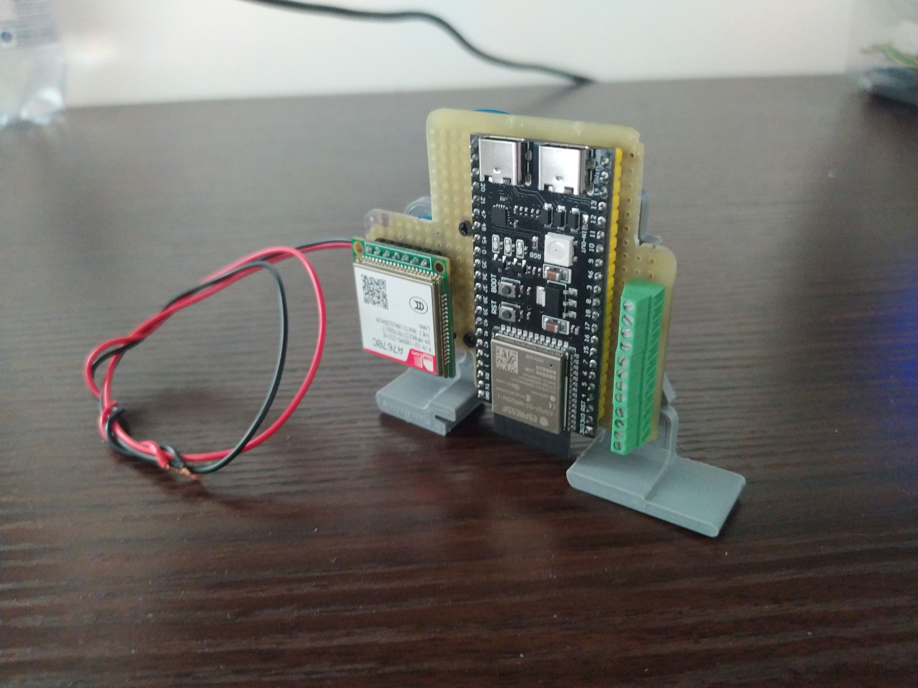
For the moment I decided to realize a demo project using a protoboard, just to test the system as a whole before realizing the final pcb. The test circuit includes a DevKit ESP32-S3, a Simcom A7670C module and connectors. That's ALL!! I decide to use internal pull-up resistors of ESP32, so no other components are involed. In some cases, the internal pull-up might not be sufficient, but for the moment It works...
This is the resullt signal when connecting esp32 with pull-up resistor. Now it’s a piece of cake!
Focus on LTE module
Fortunately, there are LTE modules available on the market (~17$) with all the necessary components, so they are practically plug&play. These boards are great to get started quickly and focus on the project right away. I chose this module because it offers the best compromise between size, price, and functionality. It's remarkable to realize that this board with everything included costs almost the same as a single LTE module if bought alone.
In particular, I was impressed by the power supply section, which uses a step-down converter to generate +3.7v very efficiently (switching). On budget-friendly boards, switching converters are not always used, and instead, LDOs are common. Additionally, the module includes a SIM socket and an optional USB port connection.

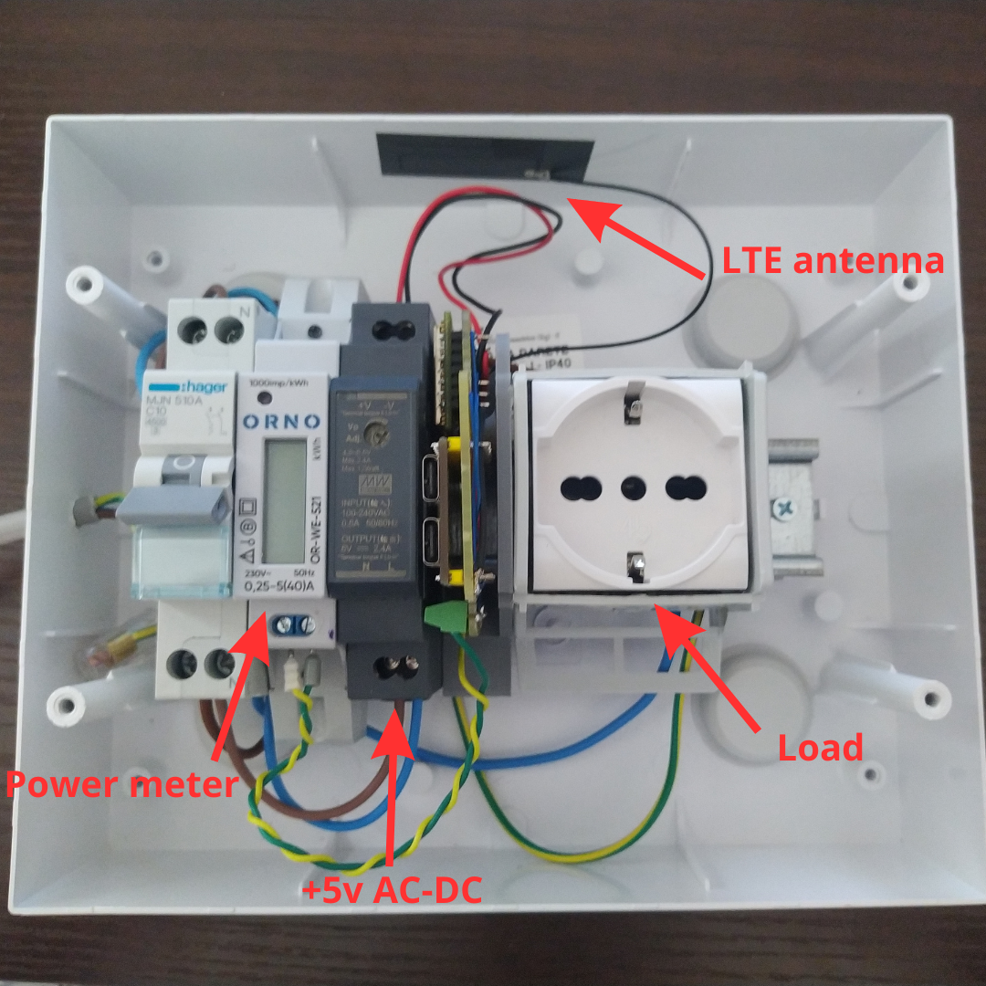
The module is powered by +5V and the power-up is controlled by two GPIOs (PEN and PWK). In addition, a third GPIO (NET) provides a connection status output. Communication with the ESP32 takes place via serial using AT commands. Network access is provided by a Things Mobile IoT SIM card and obviously an antenna.

The A7670C module provides connectivity to the external world. While sending data through ESP32 Wi-Fi is also possible, a Wi-Fi connection is not available in my target environment. In this project this module transmits data to a cloud database and receives commands via SMS.
How It works
Consumption is directly proportional to the frequency of pulses. Therefore, by defining a time window and counting the number of impulses that occur, it's very simple to estimate the instantaneous consumption at that particular moment by calculate the mean frequency of pulses. By continuing this operation over time, it is possible to determine both the total consumption and how it has changed over time.

The system counts electrical pulses from up to 10 sensors within a fixed 30-minute time window to monitor the number of pulses generated per sensor in that time period. Than converts It in Wh and store into ram. Every seven days, or by request, data stored are sent via LTE to the cloud.
The system implements SMS commands for controlling and configuring inputs and features for example:
- set number of input ( up to 10 ): name index, freq
- perform software reset
- get system status
- start and stop data acquisition
So far, the system has been tested with Orno (single-phase) meter. However, the configuration allows you to set the pulse frequency according to the meter model used. This parameter is usually indicated in the product's instruction manual as imp/kWh. It is important to set the pulse frequency correctly to obtain accurate energy consumption readings.
Currently, the online database is a simple Google Sheet where the data is arranged in a table for later analysis. Data are sent via lte using HTTP request and received by Google App Script.
The code
For this project, I decided to program the ESP32-S3 using the latest version of the IDF SDK instead of the Arduino framework. To communicate with the LTE module, I couldn't find a library that met my needs, so I preferred to write one from scratch to send AT commands via serial and receive data and events from the Simcom module. I plan to publish the project code and the library code only when I deem the project mature enough.
Future update
I've made some plans for the short term to improve the project:
- Add external pull-ups and isolations
- Make custom pcb and enclosure in din rail format
- Deploy project in a real environment with multiple meter
- Integrate a more accurate data collection and visualization system
- Add WiFi connection to make OTA firmware update