In the previous log I talked about making some significant changes to the overall design of the chassis with the goal of removing a few flaws and allowing for greater potential and utility.
Oh boy did I underestimate how much work that would be.
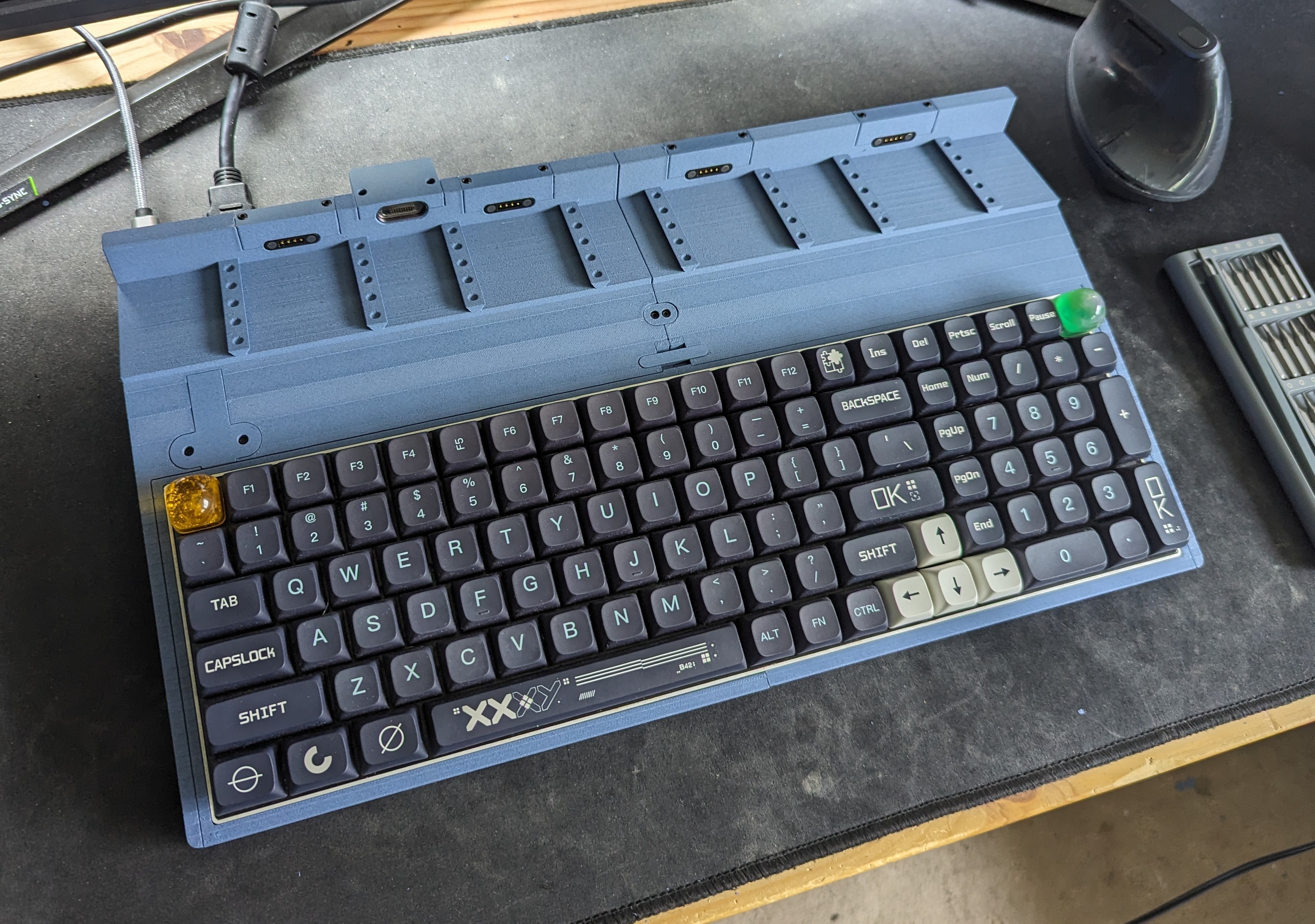
To start off, it has the keyboard tray I mentioned, but for a different reason.
I actually resolved the issue of being unable to remove some modules without first popping the keyboard out by making the 'deck' longer. By 'deck' I mean the flat area between the back of the keyboard and where the rails start.
I considered a lot of different methods for fixing that problem, but I couldn't work out any designs that allowed for quick and easy removal of the tray that would also be strong.
Furthermore, due to the slope of the whole chassis (unavoidable side effect of housing the electronics; more on that in a bit), the whole thing needs to be lifted up to slide out the tray. Not good since it weighs a lot and needs to be done semi-regularly.
The tray is just a convenient and tidy way to assemble the thing now. I could have the keyboard just drop in like in the original design, but that means the USB C cable for it would have to be loose, with a cover of some kind, which is all in all suboptimal.
A USB C plug is mounted into the chassis, and the keyboard in the tray slides onto it.
Next up is the pogo connectors.
SO, this was simpler than I thought it would be.
Currently they feed through into the sloped compartment, where they are screwed into four USB 2.0 breakout plugs, two per hub, one in each half. The hubs are just these cheapo $9 AUD ones from Amazon.
The second hub plugs into the first, which is plugged into a USB A female to USB C female adapter, giving the chassis a female USB C slot just like a normal keyboard.
I wasn't sure about the power supply of running two unpowered hubs and connected devices off one USB port, but it seems to be fine from what I've tested so far. I imagine unless you try and run an external HDD or two from it, there won't be a problem.
And finally: the HDMI passthrough.
This was probably the simplest part of the whole redesign. I used this magnetic connector, and two different flex cables and plugs, this one and this one.
Internally there is a male HDMI to male HDMI (possible because these ribbon cables and connector boards are interchangeable), and the remaining mini HDMI to female HDMI connectors will be used on the LCD module.
One of the male HDMI's goes to the magnetic adapter (right angle side), and the other goes to a female to female HDMI adapter I found lying around, which is mounted to the chassis at the back next to the USB C socket. I don't have a link to that female to female adapter, but any should work.
I considered running the LCD module via a USB to HDMI adapter, which technically works, but unfortunately the DisplayLink software does not support custom resolutions, so my 1920 x 515 LCD is very distorted and such, hence the use of an external HDMI connector on the chassis.
As for the rails, nothing has changed there. I have ideas to replace the complaint mechanism with something more resilient like spring loaded catches and smooth rails, but that's something for revision 8.
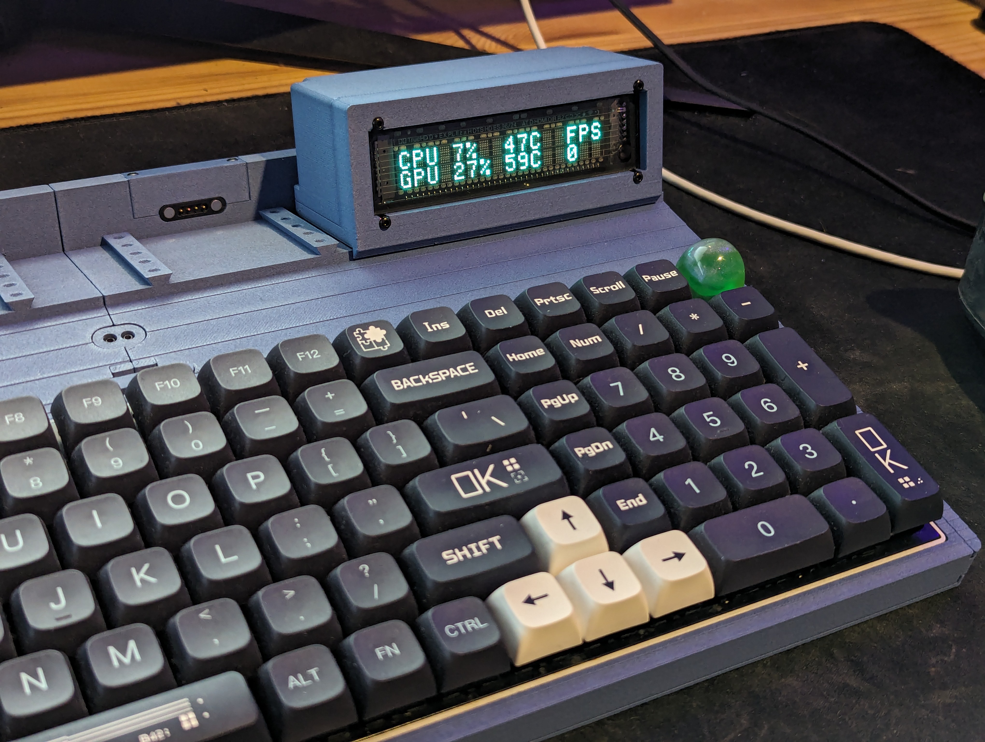
Module wise, I've tested the LCD works via the pogos for power and the adapter + passthrough for HDMI, but the only completely adapted module so far is the USB VFD, which works flawlessly (massive surprise).
At least while testing everything, I don't want to be doing a lot of soldering and desoldering, so on the modules, I'm connecting the pogos with these. Overkill and kind of huge, but the lever mechanism makes them very quick and easy to modify and assemble.
All in all, it was more work than I was expecting, but it was well worth it.
Below are some photos and a video of the thing.
Discussions
Become a Hackaday.io Member
Create an account to leave a comment. Already have an account? Log In.