Room Components:
- 3.5inch LCD TFT Module capacitive touch with an ESP32 ($15) - AliExpress
- Tuya ZigBee Temperature Humidity Sensor ($5) - AliExpress
- Tuya ZigBee Radiator Valve ($25) - AliExpress
- Ikea ZigBee TRÅDFRI LED bulb E26 1100 lumen ($14) - Ikea
- Ikea ZigBee TRÅDFRI LED bulb GU10 400 lumen ($10 x2) - Ikea
Server:
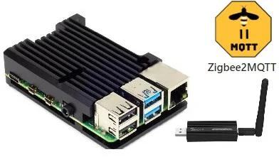
- Raspberry Pi 4B 4Gb ($55) + Power Supply, 32Gb+ SD Card, Heatsink/Case
- SONOFF ZBDongle-P Universal Zigbee USB 3.0 Dongle Plus ($20) - AliExpress (I bought the ZBDongle-P one)
Step 1: Setting Up the Display
The key component of this project is the new batch of touchscreen displays with integrated ESP32s. For $15 you can buy a 3.5 inch, IPS capacitive touchscreen TFT display with an integrated WiFi microcontroller. Combine this with a great open source project openHASP that allows a home automation control panel to be setup on these panels with just a configuration file representing screen pages. The panel with openHASP installed can then interact with other systems by sending and receiving standard MQTT messages.
The display setup involves burning new firmware on the screen, connecting the screen to the network and then uploading the room control panel page.
- This procedure is for the Sunton ESP32-3248S035C, other screen that are compatible with openHASP can be use. For another screen follow the instructions on the openHASP Flash page. For the Sunton ESP32-3248S035C follow the instructions below.
- Download the firmware from ESP32-3248S035 - openHASP (recommended nightly builds Install openHASP).
- Download the Tasmota flash tool to allow flashing the firmware to the screen (this and alternatives also covered in the openHASP Flash page).
- Connect the Sunton ESP32-3248S035C to your PC USB port with the supplied cable (if the screen is not recognised you may have to install the serial port drivers for the CH340C)
- Run the Tasmota-PyFlasher-1.0.exe, select the serial port for the ESP32-3248S035C, browse to the downloaded bin file, select yes to erase the flash and then click on the Flash button.
- Restart the screen and follow the instructions on the openHASP site to setup the WiFi SSID and password on the screen.
Step 2: Setting Up the Control Page

You should now have a working screen but with some sample controls. Next we want to upload the configuration page with the room heating and lighting controls.
- Download the attached pages.json file that contains the panel configuration page.
- Restart the screen and note the ip address of screen when openHASP starts (e.g. 192.168.0.10)
- On you PC, open a browser and enter the ip address, this will show the openHASP configuration options.
- Click on the File Editor button and select the pages.jsonl file on the left side panel.
- Delete the entries in the pages.jsonl file and paste in the contents of the pages.json file
- Click the Upload button, then Clear Pages button, then Reload Pages button. The heating and lighting panel should now be displayed.
Step 3: Setting Up the Raspberry Pi Server
The touchscreen control panel needs some way to send and receive messages to and from the Zigbee devices. The panel communicate using MQTT messages and the devices communicate using the Zigbee protocol. This means we need an MQTT broker and a zigbee to MQTT translator. For this server I am using Mosquitto for the MQTT broker and Zigbee2MQTT.
When we get a message in from, for example, the temperature sensor we need to have something to decide whether the heating should be activated. In this project I am using Node RED which is graphical way of creating process flows with small scripts to process the input and decide on the output (e.g. temperature is below 18C so open the radiator valve).
So we need Mosquitto MQTT broker, Zigbee2MQTT server and Node RED. If you have these already available then you can skip this step. You can also install these individually on various platforms but I would recommend following the Andreas Spiess guides here and here to install or follow the information on the IOTstack web site. IOTstack provides many of the applications you need for home automation all on one Raspberry Pi with much of the configuration and installation work provided and with a support web site and discord channel if you get stuck.
Andreas' guide covers setting up Mosquitto and Node Red. I would recommend Influxdb and Grafana in his guide as well but they they are not essential for this project, just useful for storing and charting sensor and state data. If you are installing using IOTstack then include Zigbee2MQTT but configuration is not covered by his video guide (although it is covered in the IOTstack guide) but I will cover this in the next step.
Step 4: Configuring the Zigbee Gateway
I am using the Sonoff Zigbee 3.0 USB Dongle Plus (Dongle-P) as a zigbee coordinator along with zigbee2mqtt. Before use the zigbee dongle should be re-flashed. This process is detailed in the devices part of the web site but I found the youtube guide from Mark Watt covering this zigbee dongle to be the simplest and clearest way of upgrading the firmware.
To upgrade the firmware watch Mark Watt guide which covers:
- Unscrewing and removing the zigbee board from the dongle housing
- Download and extract the coordinator firmware 'CC1352P2_CC2652P_launchpad_router_20220125.zip' from Koen Kanters github site
- Download the flash programmer from Texas Instruments site (this will require a registration).
- Plug in the USB zigbee dongle while holding down the boot button as shown in the video.
- Start the TI flash programmer selecting the dongle type CC2652P, Tick Erase, Program and Verify and ensure that the Disable Bootloader check box is unticked.
- Click the Play icon button to upgrade the firmware.
- On completion remove and reassemble the dongle
Assuming zigbee2mqtt was installed as part of IOTstack it now needs to be configured.
- Plug the zigbee dongle into the raspberry pi and restart (sudo shutdown -r now)
- Identify the dongle by running ls -l /dev/serial/by-id
- Copy the identifier which will be very similar to mine: usb-Silicon_Labs_Sonoff_Zigbee_3.0_USB_Dongle_Plus_0001-if00-port0 -> ../../ttyUSB0
- Open the docker-compose file for editing by running: sudo nano ~/IOTstack/docker-compose.yml
- Replace the device mapping with: /dev/dev/ttyUSB0:/dev/dev/ttyUSB0
- Open the zigbee2mqtt device configuration file by running: sudo nano ~/IOTstack/volumes/zigbee2mqtt/data/configuration.yaml
- Change the port port to: port: /dev/ttyUSB0
These steps are covered in detail by the videos and web site but these steps worked for me.
To verify check the zigbee2mqtt status and logs using the verification and faqs