 jefmer
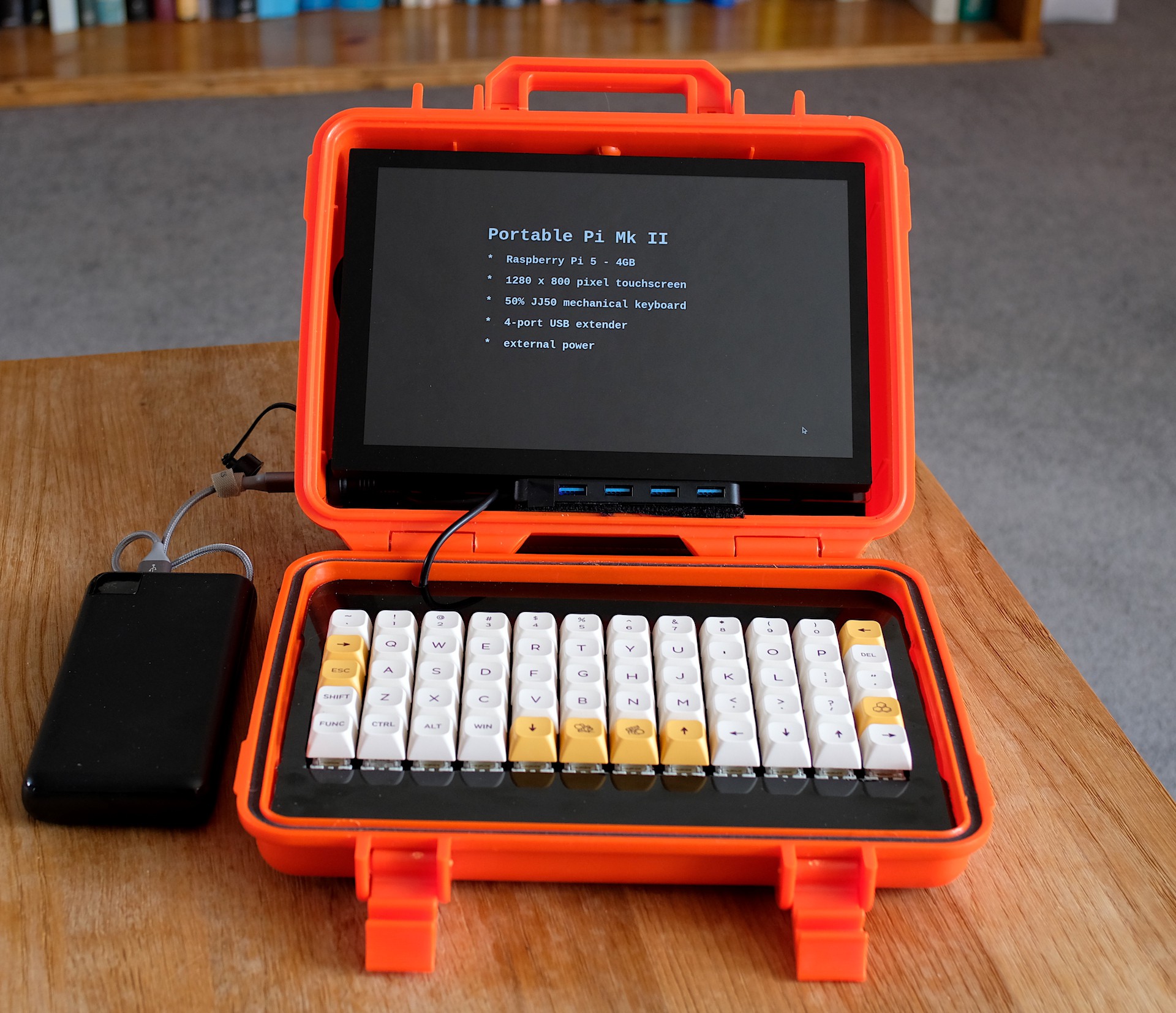
Case
The most visible difference with Portable Pi is the new bright orange case. Unfortunately, the new display with its larger surround did not quite fit the original Casoman case. The new case (95.4 x 275 x 203mm) from Maplin was available in black or orange - I chose orange to distinguish it from the previous Portable Pi, however, I am not sure that was at all the right choice:).

Visible in the photo above is the USB C socket that provides power to the Pi 5.
Keyboard
This is a 50% ortholinear mechanical keyboard based on a JJ50 PCB from KPRebuplic.

I chose this PCB as firstly, it is currently the only accessible example of a 50% keyboard and secondly, it had a keyboard definition in the QMK firmware repository. The PCB is pictured below:

As you can see, it has a USB C connector not the mini USB connector pictured on the KPRepublic website. In fact this is an upgraded V2 of the JJ50 with an Atmega 32U4 processor and not the V1 with an Atmega 32a processor as advertised. I would have been pleased with this upgraded version had I not immediately flashed it with what is V1 firmware from QMK and essentially bricked the board. Luckily, in fact not completely bricked, as the bootloader showed up in QMK Toolbox.
KPRepublic pointed me to their bootmapper software, however, I could find nothing relevant to the JJ50 so after recovering from my initial despair, I resolved to create a new JJ50v2 definition for QMK. To do this I needed to find the Atmega 32U4 pins connnected to the key switch matrix. I managed to do this by a combination of visual inspection and continuity testing with a multimeter and I was very happy to reflash the board with working firmware. I subsequently found a closed pull request for JJ50v2 that had not been committed to the main QMK repository on Github - so I could have saved myself some considerable effort and anxiety! For anyone interested in the JJ50, you can find the matrix here. For convenience,they are:
#define MATRIX_ROW_PINS { D3, D5, E6, F1, F4 }
#define MATRIX_COL_PINS { B1, B0, F7, F0, C7, C6, B6, B5, B4, D7, D6, D4 }
I used my usual Gateron Yellow switches to populate the keyboard, however, I made the mistake of ordering 3 pin versions which are no good for soldering into a PCB with no plate to align the switches. I evetually got the right 5 pin switches from MechBoards and the result is shown below.
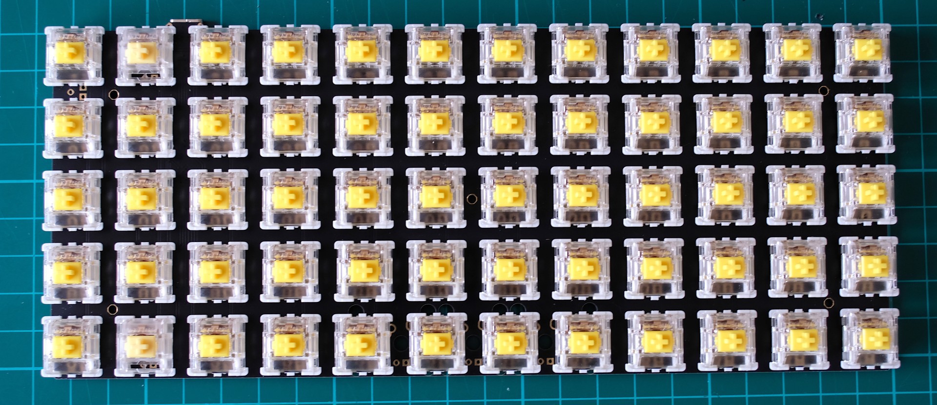
I did not use a plate as there was none available so there is quite a lot of flex in the PCB when you press a key. Initially this resulted in a unpleasant plastic clattering noise from the keyboard before I packed some stiff foam under the PCB which restored the dull "thwock" sound that I prefer.
Display & Raspberry Pi 5
The display is a an ELECROW 10 inch 1280 x 800 HDMI touchscreen available from Amazon. It has mounting points on the back of the display for a Raspberry Pi and it can be powered from a Raspberry Pi USB port.

I glued some perspex strips with brass spacers to the back of the display as I did not think the four mounting points for the Raspberry Pi were enough to support the display on its perspex back plate as shown below.
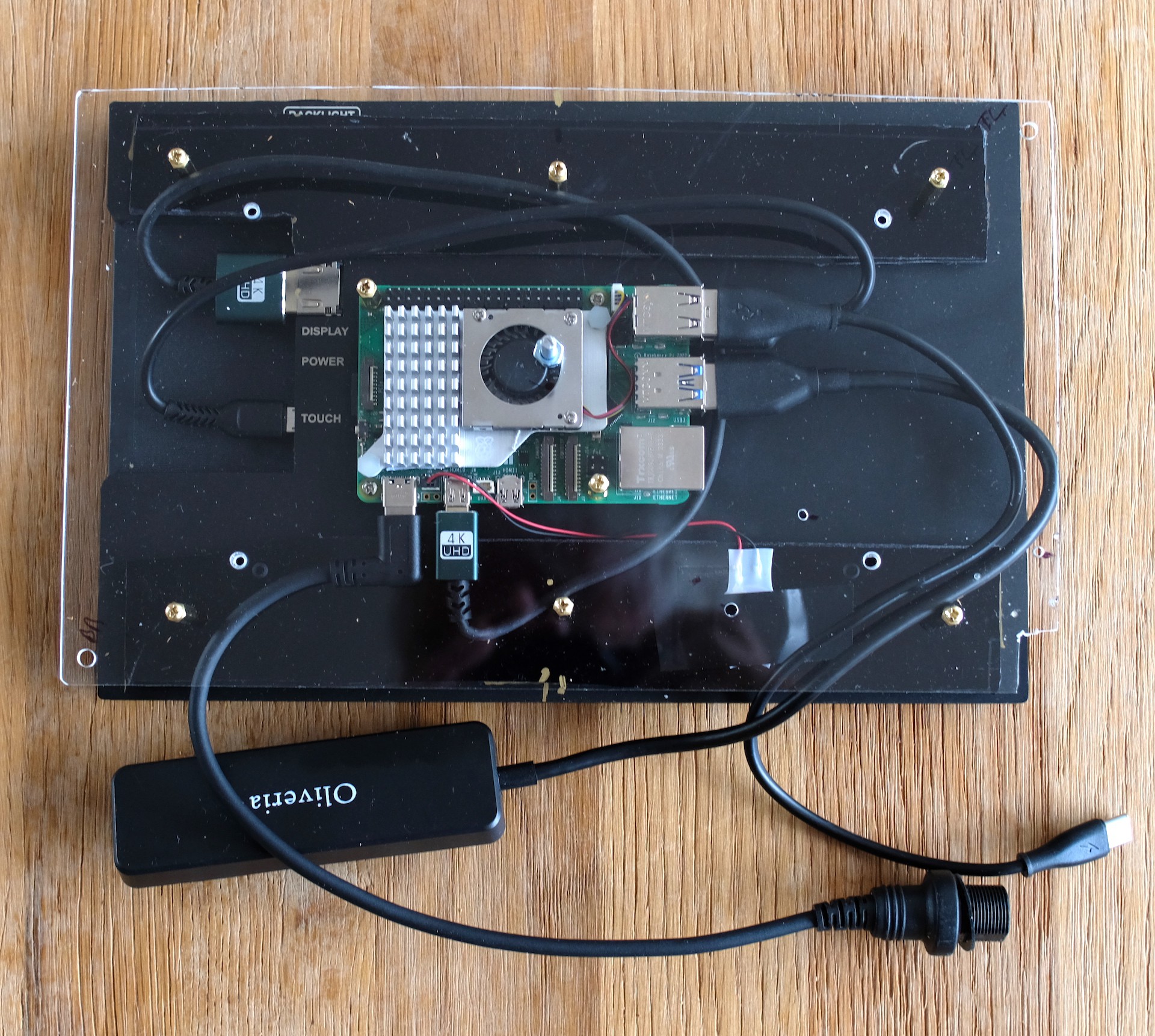
There is enough of a gap around the display to ensure good airflow to the Raspberry Pi cooler and in addition enough of a gap at the bottom to velcro the USB port extender to the side of the case. The foam at the back of the case provides some shock absorbing protection for the display which is held into the case with a a single bolt. You can see the stand offs that support the keyboard in the picture below. Since taking this picture I have added a layer of foam to better support the keyboard PCB.

Power
I was unsure on whether a cheap powerbank such as the one that I used in Portable Pi would be sufficient to power a Raspberry Pi 5, so I opted for the simple solution of relying on an external power source. The new version of the Recovery Kit has found a powerbank that works with a Pi 5, however, this is very expensive ( £199 on Amazon UK`). The 27AH powerbank pictured above does seem to work ok and claims to provide up to 4.5A at 5V from one of its USB A outlets - it currently costs £20 on Amazon. The Recovery Kit does include an SSD drive and I have not tested this cheap powerbank with an SSD drive and a display.
By setting POWER_OFF_ON_HALT=1 in the Pi's EEPROM, software shutdown powers off the display and the port extender and the powerbank button can be used subsequently to restart the Pi. I have also set `usb_max_current_enable=1` in `config.txt` to avoid the Pi limiting power to the display.
Conclusion
With this project - I am now Raspberry Pi complete, with a Pi 4 based tablet, Pi 5 based portable and a Pi 5 with NVMe SSD drive for my desktop, so many thanks to those that have shown an interest in my previous projects - I think this will be it for a while.