 esben rossel
There are two (possibly more) good reasons for using a separate power supply for the TEC cooled linear CCD.
- The computer's USB will be unhappy to power the peltier-element.
- The opamp requires ±5V to operate
The PSU consists of a small ±6V 10VA transformer for the CCD-circuitry, and a slightly bigger ±6V 24VA for the TEC alone. I've chosen to use two separate transformers to avoid an (inevitable?) asymmetric load if the TEC was to be powered by one of two outputs of a single larger transformer. (If this reason is invalid it's because I'm a whale biologist chemist and not an electrical engineer).
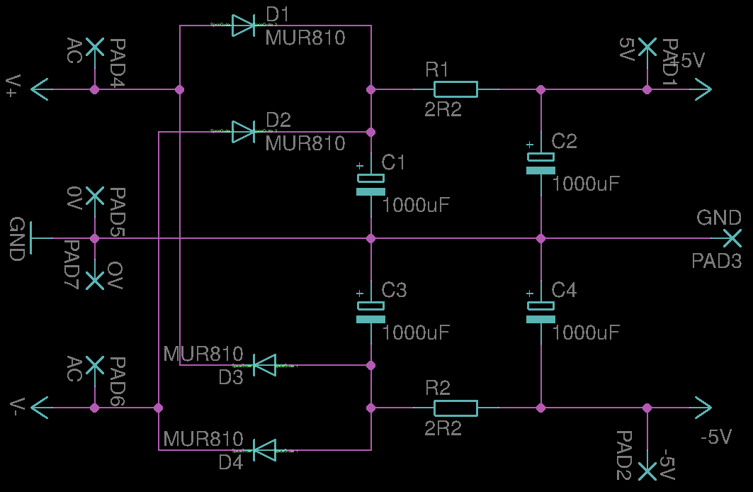
The CCD PSU
The CCD PCB has separate linear regulators (79L05 and 78L05)¹ for the analog and digital parts of the circuit that are all fed the same unregulated ±6V from the RC-filtered output from the small 10W transformer.
The current draw is < 30 mA, so the voltage from the PSU will hopefully stay above 7V, or the regulators will drop out.
The schematic is here:
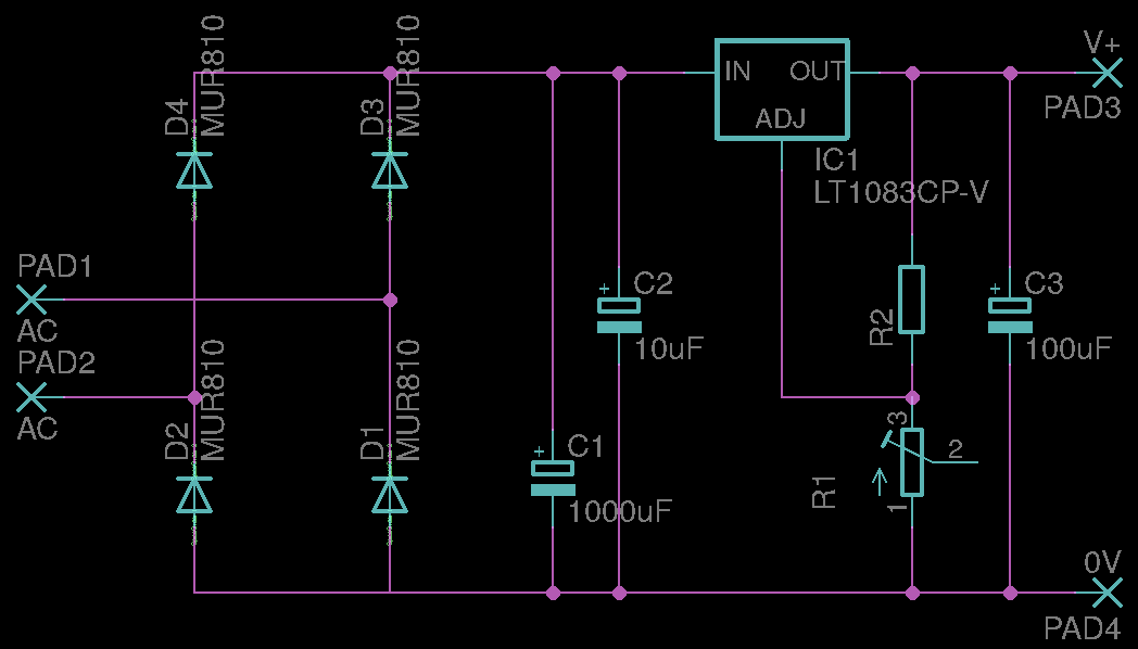
The TEC PSU
Is regulated with an LT1083 to make sure it the TEC's max-voltage (4.2V) is not exceeded. The schematic is:
And here they are, all boxed up:
[insert pretty pic of the psu]
[1] It's a bad choice for more than one reason, I know. Expect to see a LT1964/LT1761 or similar if I ever decide to improve upon it.
Discussions
Become a Hackaday.io Member
Create an account to leave a comment. Already have an account? Log In.