 kelvinA
I can think of 3 ways to go about a controller solution for #Tetrinsic [gd0041]:
- The expectable way: A small, low-cost MCU on the same PCB as the angle sensor and BLDC driver.
- The exciting-on-paper way: A BLE module on the same PCB as the angle sensor and BLDC driver.
- The monolithic way: The angle sensor on its own and all control via a single MCU on the main board.
Now I say "exciting on paper" because it would make Tetoroidiv a bluetooth- and zigbee-enabled servo. The reasoning is because of the benefits they offer: the modules are off the shelf (thus simplifies assembly and testing) and it then means that the main board (e.g. the Tetent/Tetrescent PCB) doesn't need an additional BLE module.
The "expectable" strategy means that 3 different microcontroller toolchains would be needed for the final product, whereas the "exciting on paper" strategy would reduce that to two and simplify the design of the main board due to more PCB surface and trace space.
The monolithic way would need 2 toolchains too since there's not a bluetooth and LCD-controller enabled microcontroller, but would allow better utilisation of the peripherals in the U5G9. The downside is potential SPI-bus bottlenecks.
ESP32C6
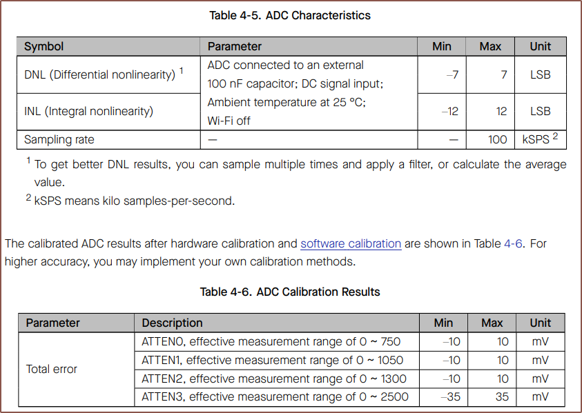
Understandably, the strategy I originally thought of was the ESP32C6, as it's only about 50p more than the ESP32C3 and has more features (including a motor peripheral, allowing 6PWM motor control if needed) whilst keeping the same sized module. My main reservation was that the ADCs that Espressif make have a poor reputation. It took a while to even find the characteristics, which weren't in the larger Technical Specifications.pdf but in the smaller datasheet one:
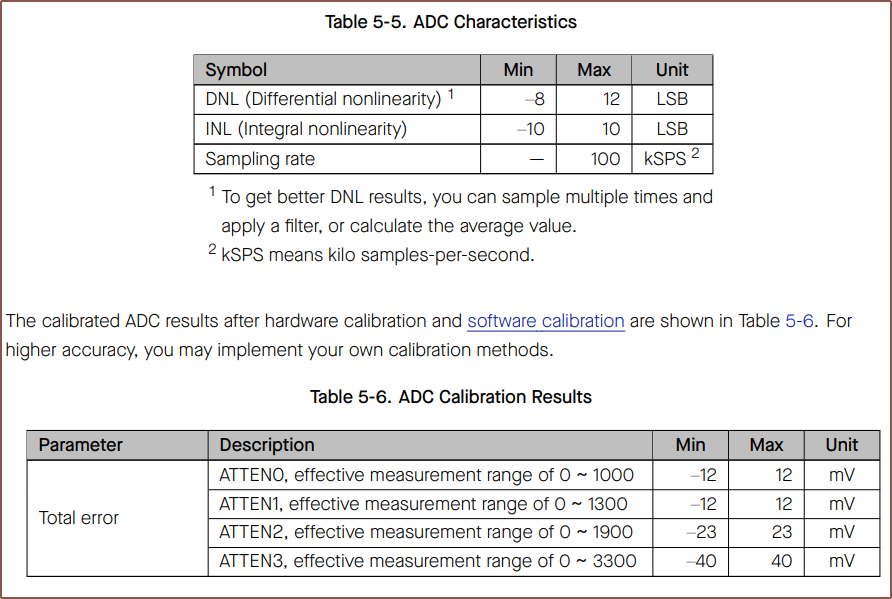
They seem very similar to the C3 ADC:
Now I looked into SimpleFOC and hear that the C3 is kind of decent. I've also now done some research on what those DNL numbers mean and it turns out that lower is better. It basically means the tolerance around the correct digital value. For example, if a 1.0V analog signal should be converted to the number 1000, the C3 could actually read between 993 and 1007. I still have yet to fully understand what INL represents.
nRF52833
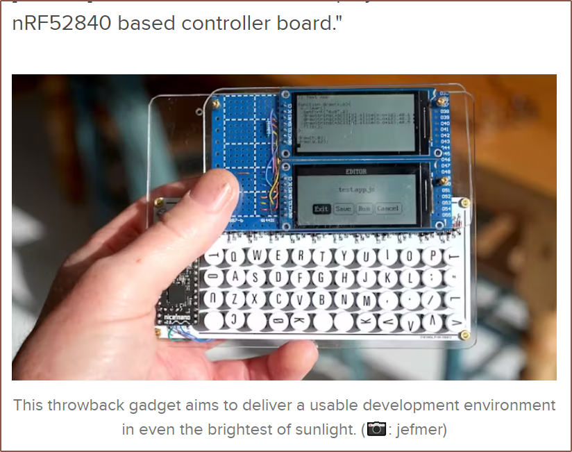
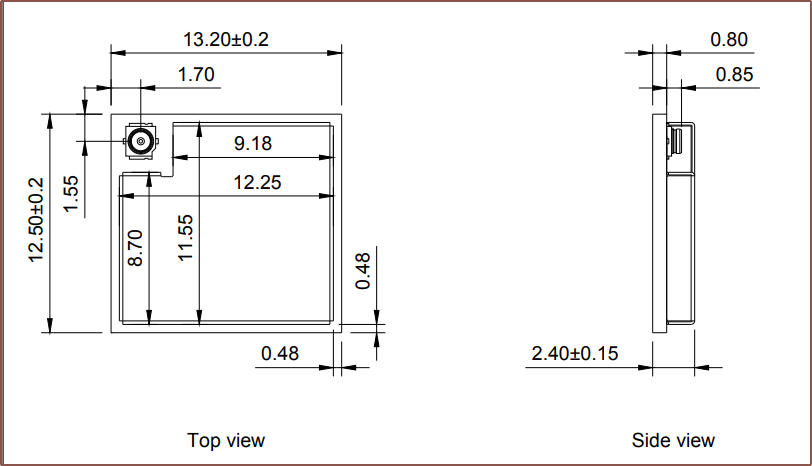
Anyway, I was reading about PDAs powered by microcontrollers (such as the one above) and remembered that the nRF52 line of chips also existed so I went to go see what the smallest module was and I found this:
This module has an antenna pin should I need it, but the whole thing with antenna is smaller than the C6 without so I will try using the PCB antennas first. This module is over 2X that of the C6, but in absolute terms, it's about £20 per pair of Tetents.
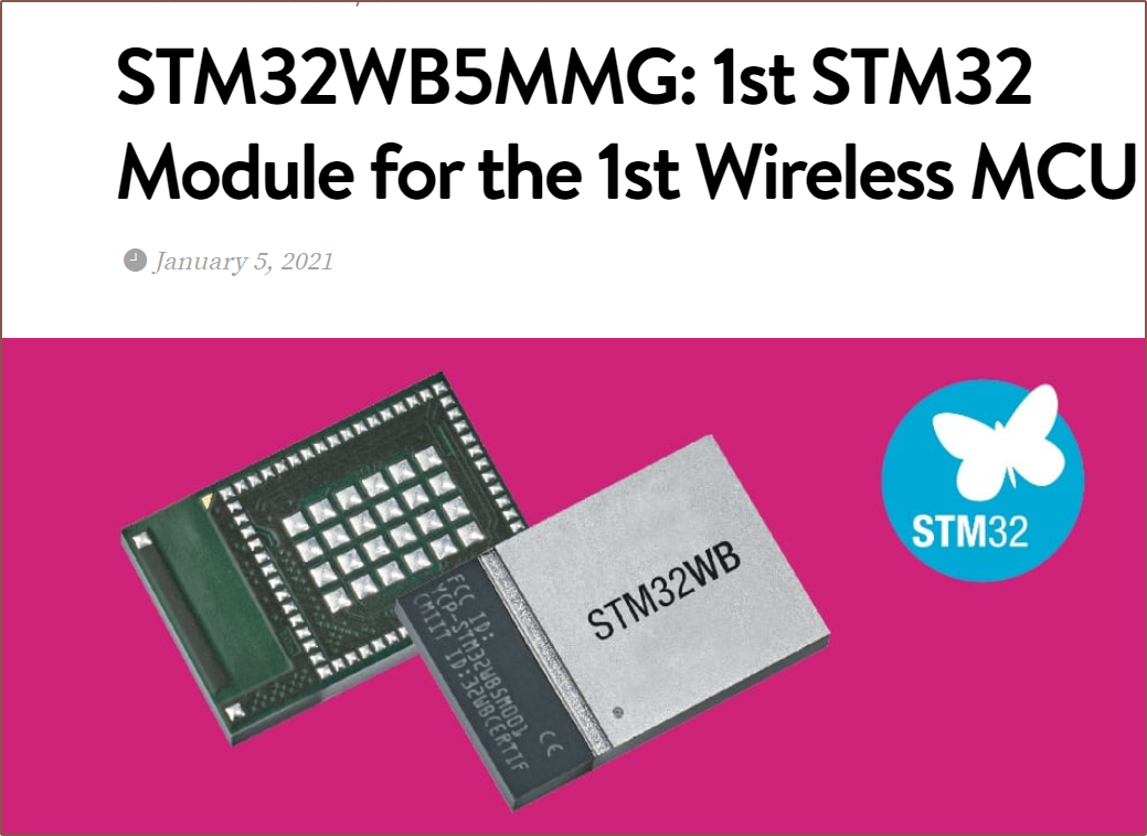
I've also heard that STM32s have good ADCs, and the STM32WB5MMG is a module that only comes in at 7.3 x 11mm, but the price seems to be over £9/ea.
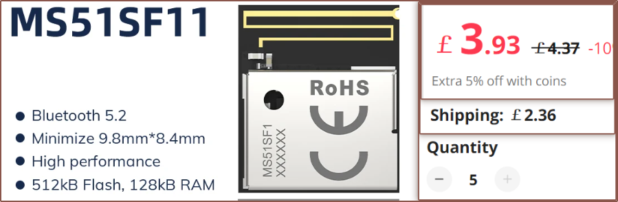
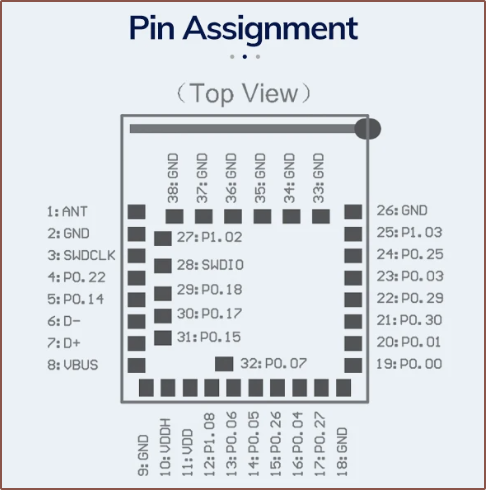
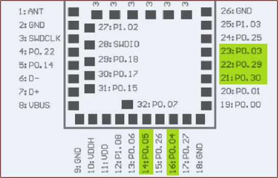
Back to the SF1 module, it does seem that there would be enough pins to reasonably connect all components:
Additionally, like all the other chips and components, it can run off 5V:

It also seems to use 2-wire firmware upload, whereas the C6 would also need a BOOT and RESET pin (since there's no space on the board for buttons). Additionally, there is a Rust HAL for the nRF52 chips.
The ADC sounds good. For starters, it supports 8 single-ended channels or 4 differential channels, as well as oversampling. It sounds closer to the specifications of a discrete ADC than what feels like an afterthought in the Espressif line. It seems that, instead of the C6 having to compute the average of the input signals, I'd be able to do something like set a 16x oversampling and achieve 4kSPS per channel (thus 192kSPS total speed), where that specific sampling frequency is chosen to match what was used in the YouTube video of this servo project:
My plan is to target a minimum realistic speed for everything from sensor acquisition to motor control, and 4kHz sounds like a reasonable frequency to aim for.
The module itself seems to have 5 of the 8 analog pins exposed:
Thus, it's possible that an analog method for sensing the rotor orientation (SinCos voltages) could be used with 5kSPS/channel and 8x oversampling. It's probably better to get an all-in-one chip though.
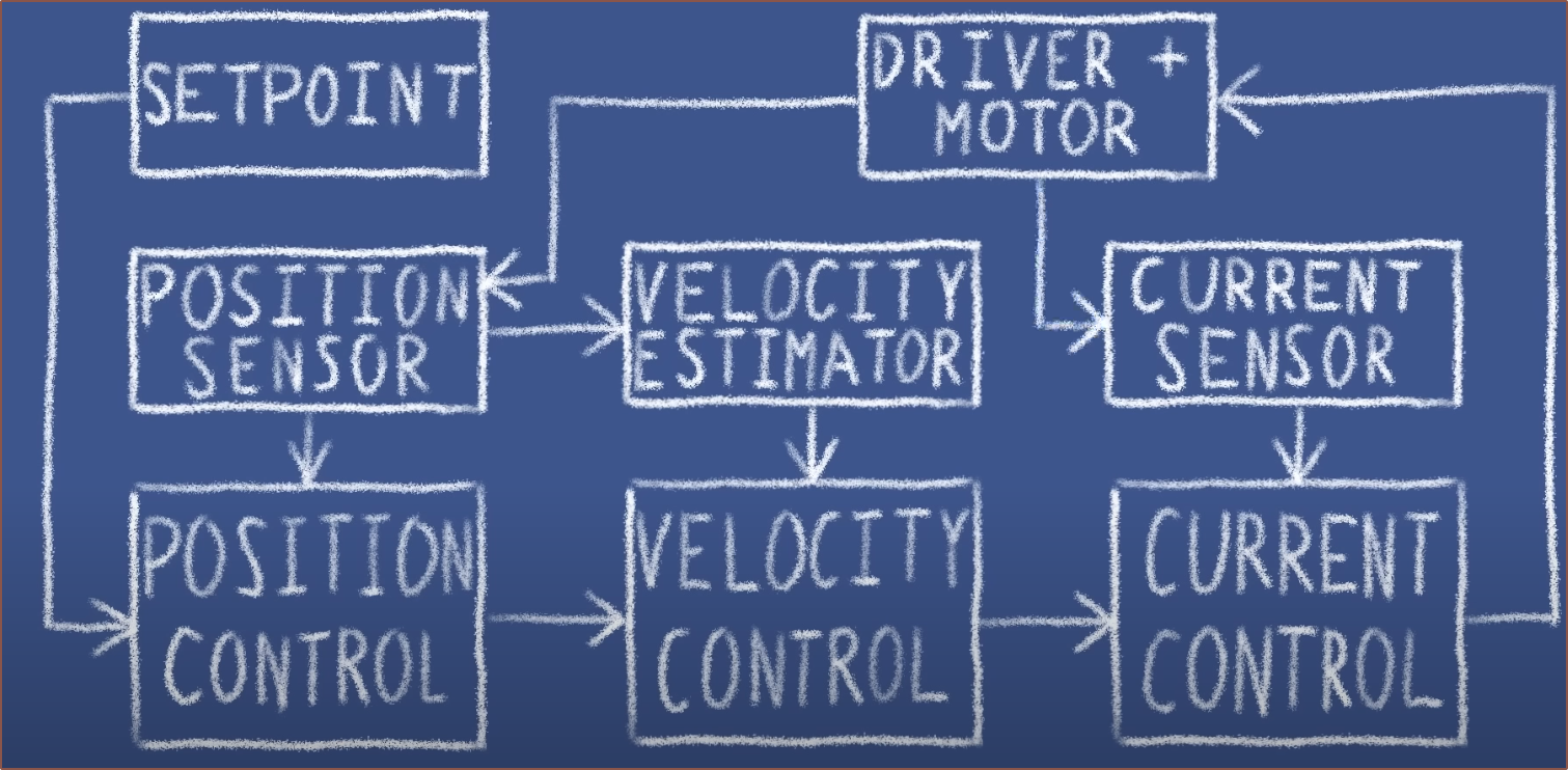
[May 21] This article on the FOC algorithm suggests that the steps are executed between 15 - 20kHz, so it sounds like I should do 4x oversampling for 16kSPS/channel. SimpleFOC just says "the faster the better" in a comment in its sample code, also noting that the "Arduino" can do 1kHz and the "Blue Pill" can so 10kHz.
Discussions
Become a Hackaday.io Member
Create an account to leave a comment. Already have an account? Log In.