 mkdxdx
I'm fascinated by light shows and flashy installations on concerts and how they blink in sync with music and all.
I've also been into long-exposure photography for a while, whilst cobbling together contraptions to "paint" pictures in front of a camera in the dark.
So, naturally, I'd eventually need some tools that do not fall apart and that scratch that bright itch of mine, and this project is basically what happens when there is almost too much spare time to make things come true.
Fun things first - this is what the project was able to do at it's latest state.
I will imediately spoil the magic - there is no AI and no clever procedural generation on the fly.
This video is an elaborate test setup to see if project is able to render hand-crafted Vixenlights show over 96 RGB LEDs with comfortable to watch framerate over proprietary 2.4GHz link that NRF52 MCU offers (ye, it's ESB) in direct line of sight and 1m of distance between two trancievers.
But oh boy have i had fun cobbling together that mini-scene and making that show timeline in Vixenlights!
An approximate visualization of a setup above (that will segue into more details):
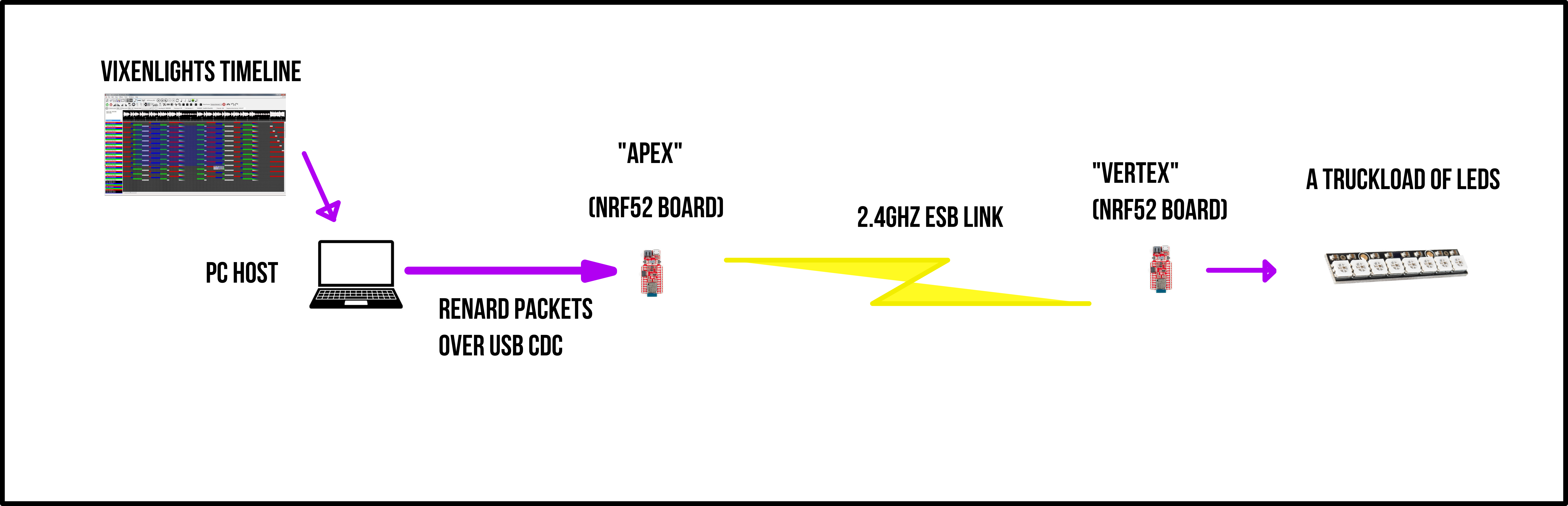
Vixenlights software (look it up, it's not made by me, but by awesome people) renders the effect timeline that is synchronized to a soundtrack on PC.
Some early iterations that show how timeline looks:
That render result is converted into values for scene lights (or pixels) which then converted into Renard protocol (look it up also - it's not mine).
Renard protocol packets are sent over USB to NRF52 board that exposes virtual com port class and parses these packets to acquire RGB channel values.
These RGB channel values are then mapped to a current configuration of paired vertex nodes - each node can have it's own "place" within global rendering buffer - custom channel offset, custom channel count and such - and board will cut that global buffer accordingly and send to each vertex data that is designated to it - that is, if vertex is in "non-autonomous" mode.
RGB data that is designated for said vertex is then encapsulated into simplest packet form and sent over ESB link to that actual device - to be interpreted according to it's output type (is it a smart led? is it dumb PWM-driven LED? is it a LED matrix?) and then rendered out to light up the night.
Simple!
There can be more than one vertex, but only one apex can lead them.
There is "pushbutton pairing" feature available to pair more - you will get no address collisions if you're lucky.
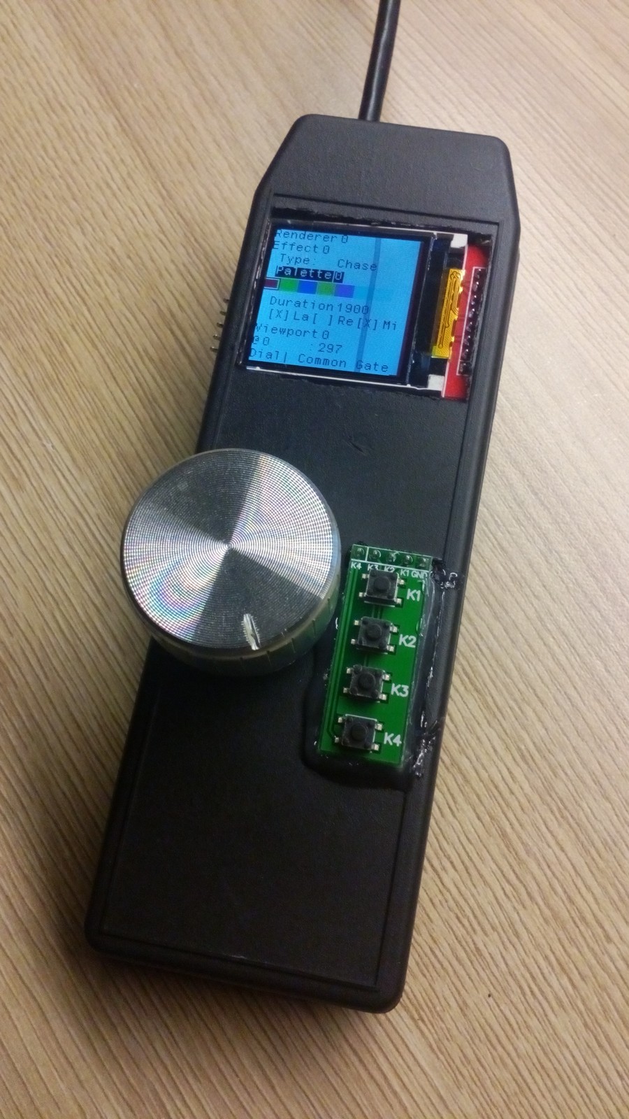
Btw this is what Apex looks like currently - this was designed before i've got my hands on a 3d printer. Subtractive manufacturing was all the rage.
For some reason I don't have any of the Vertex node pics, so imagine a NRF52 devkit with a sting of smart leds attached to it - there is not much to look at.
But here is some more results instead that touches that long-exposure photography business:
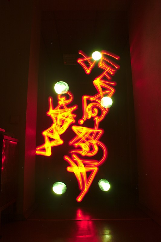

In setup above, Apex generates LED colors for Vertex without host, which is then used with a different setup that includes flashlight-style reflector to paint a picture in the dark.