 Scott
ScottWith the PCB’s on order and the mechanical dimensions taken, I was able to start on laying out the front and back panels for my design.
I used an old version of AutoCAD, which I had learned back in the mid-80’s. I don’t use it much these days but sometimes it comes in handy.
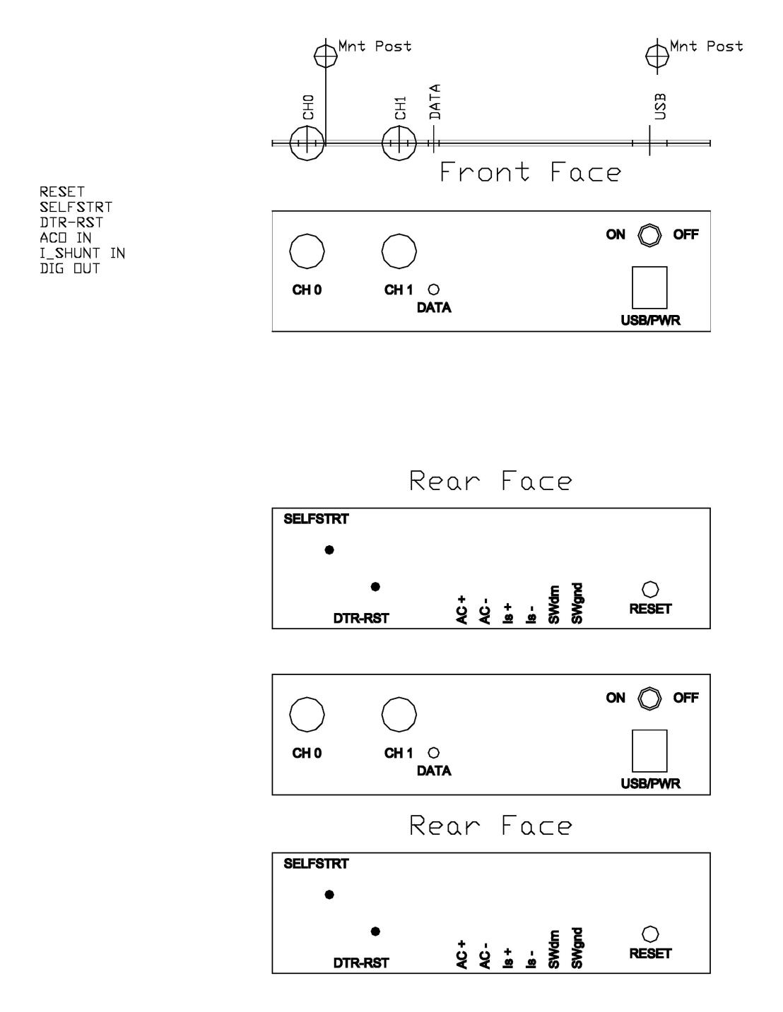
The original front panel was used and all I added were the holes for the “ON/OFF switch”, Channel 0 and Channel 1 inputs. The square hole was just the right size to fit a USB mini-B plug through and was used to access the USB mini-B jack located right behind it on the PCB. Also present on the original front panel was a small whole, which had an LED behind it on the original device’s PCB. I used that as well by placing an LED behind it.
The back panel was cut from a larger sheet of plastic that I had acquired at the local “surplus electronics” store. It was a soft plastic that had a smooth side and an “orange peel” side. It took no effort to drill the holes using my drill press and the 1:1 alignment guides I printed. Below is the JPEG image of the front and back panels after I decided what mechanical components to put where.
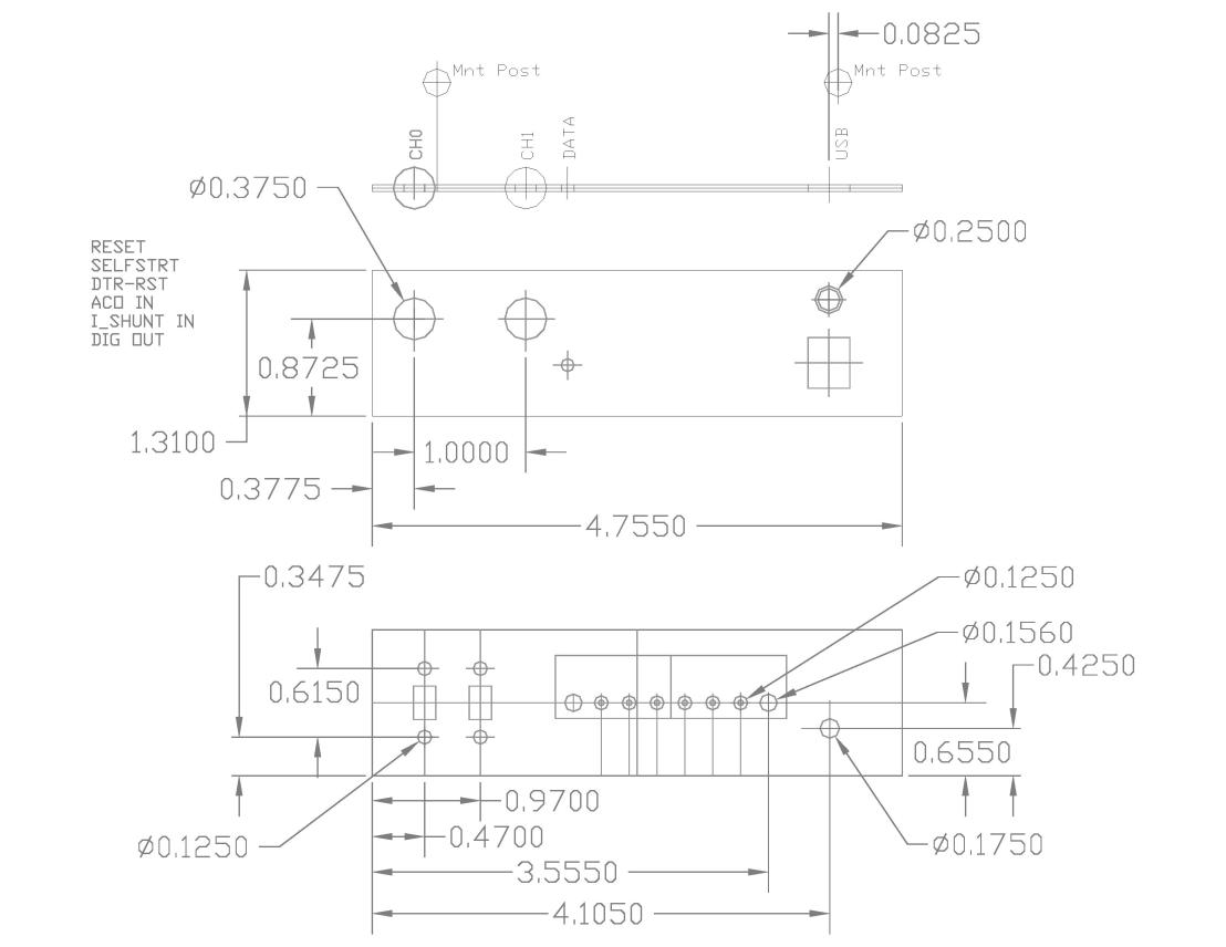
I also used the annotated 1:1 drawing printed on a full-sheet label, which I applied to each of the faces once the holes were drilled. This made a nice legend for each of the two panels.
Since the AVR is using OptiBoot (part of the ARDUINO IDE support files) for it’s boot-loader, I added a switch to enable switching in and out the DTR signal from the USB-to-Serial bridge. The DTR signal is used to pulse the RESET line of the AVR to initiate the boot-loader for programming. However, in debugging, the ATmega328P uses ATMEL’s DEBUG-WIRE® protocol and having the DTR signal connected causes DEBUG-WIRE® not to function.
The 2nd switch is used to tell AttoBASIC, which the AVR Data Recorder is using as it’s “operating system”, whether or not to auto-load and run the 1st program saved in EEPROM. Using this method, the AVR Data Recorder can be used as a “stand-alone” device or in “interactive mode”.
Below is the JPEG image of the legend text.
Discussions
Become a Hackaday.io Member
Create an account to leave a comment. Already have an account? Log In.