Edward Li
-
Losing my head!
04/21/2017 at 19:17 • 0 commentsHello dear readers and..
![]()
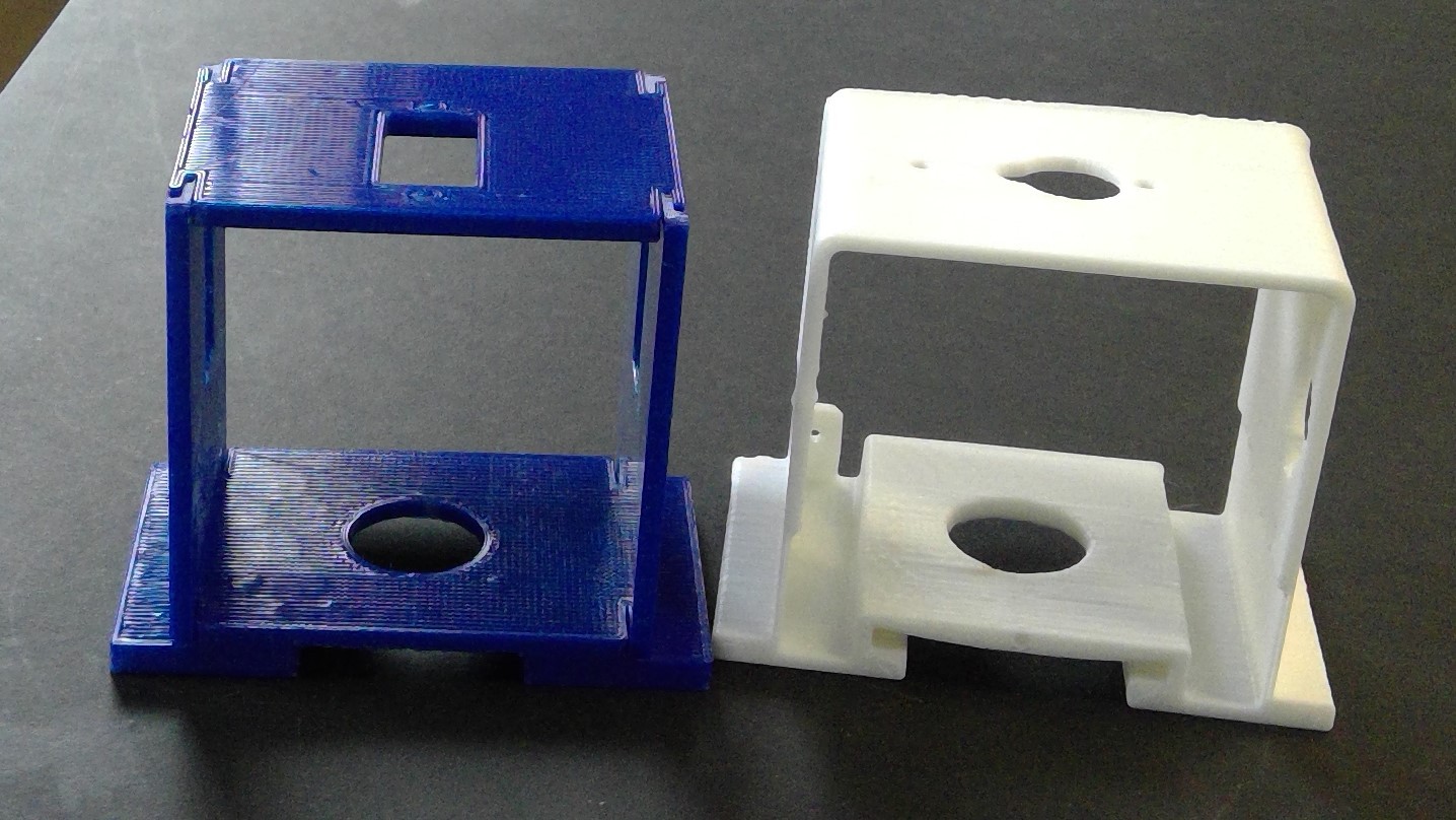
Last time i had show you guys some of my achievements like finishing the design of the new body for the Barnabas bot. Although that was a big achievement for me, it still was imperfect since it did not get into the actual issues of the PCB board mount that Eric and i need to work together to get it working. On top of that, Eric was very picky about how the height of the bottom base was not to his standards so back to Fusion i go!
![]()
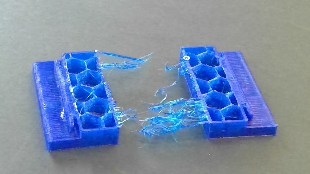
After i finished my wonderful adventure to the lands of modeling i went straight to printing. But of course, mistakes were very much made that day when i forgot to add support material...
![]()
I am a very intelligent man...
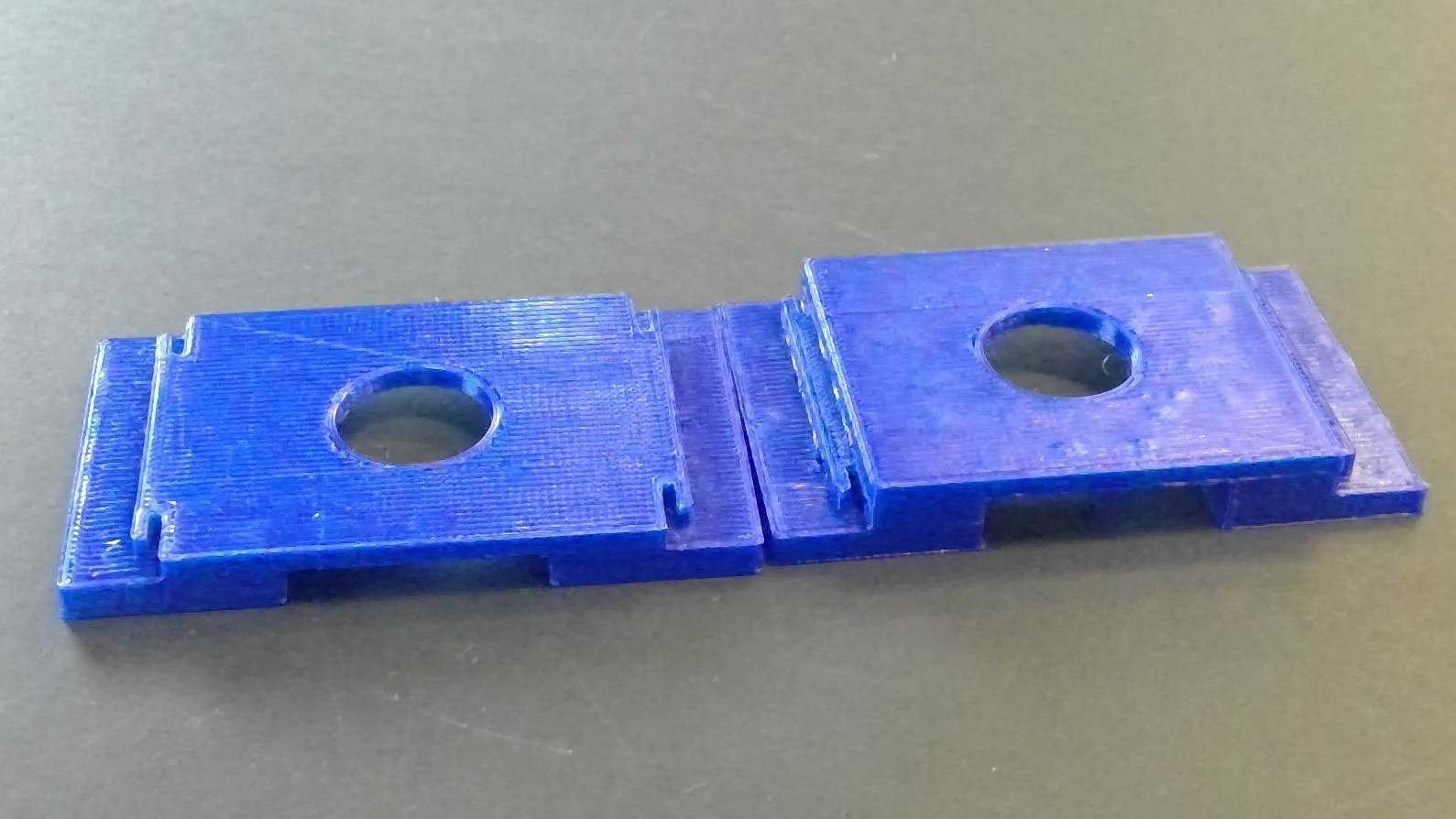
But fear not viewers! I have corrected my mistakes a produced a base worth of Eric's praise!
![]()
Ah yes, what a master piece.
![]()
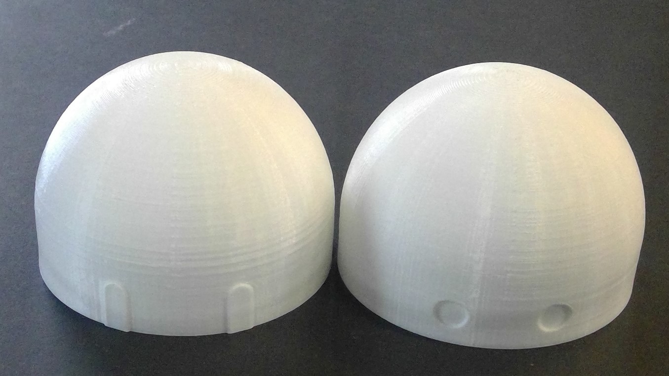
But i'm not stopping there! Although the body is practically done, we still need to make the entire robot injection molding ready which means i need to update the old one to newer versions. and here's the runner up...
![]()
Now here's the thing, the idea of injection molding is similar to ice cube trays. If you were to make a tray to create these heads, would it come out? Well by theory the one to the left would but the one on the right would not because of the fact the eyes are indented inward which would provide an issue in terms of mass producing these. Additionally, i won't stop with just the left one, i'm still making different versions that will let us have a larger variety to pick from.
But for now, until next time!
![]()
-Ryan
-
Finished?
04/18/2017 at 20:49 • 0 commentsHello people of the internet and...
![]()
(To be perfectly honest i think this is how i'm going to start my posts from now on)
In the last post i showed the servo mount to be working but when it comes to injection molding, it's another issue. My original plan for injection molding was using an aluminium mold that would be created via milling. Ah yes, but there was an issue. Our milling machine only has 3 axis which means the slanted curves for the interlocking joints is useless and needs to be changed. So after a long attempt to change how it works, i found that a tab system would be better than slanted. Therefore no matter what option we chose for the mold, it would turn out fine.
![]()
Now, moving beyond that, i had to do a lot of reading to understand how injection molding works. Dan, the resident engineer, was kind enough to give me the $2400 book about injection molding.
![]()
After reading the table of contents, my face turned to this...
![]()
Yup, i have almost no clue what i read but i did understand the basic procedures of it. And on top of that, i'm a month ahead of schedule since the molding machine is not up yet.
![]()
But just because i'm ahead doesn't mean my job is done. So back to Fusion 360 i go!
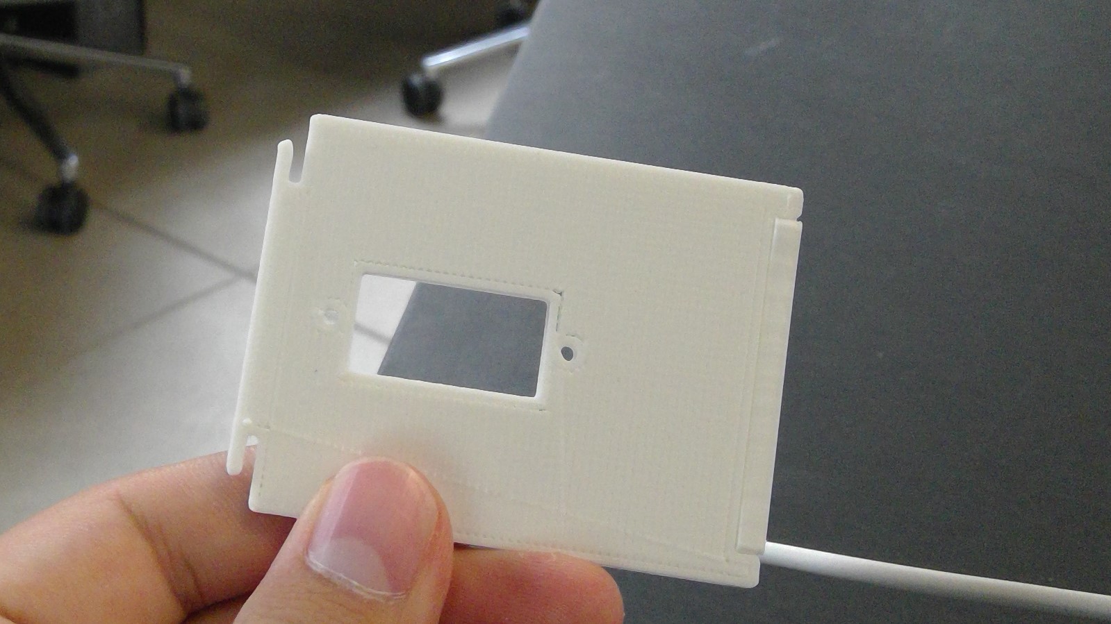
And after multiple different versions of my body, I was able to create the positive of my mold.
![]()
Nice
![]()
This is where ill leave for this week, bye bye
![]()
-
Onward and upward -Eric
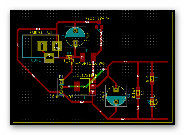
04/15/2017 at 21:37 • 1 commentSo since I last checked in with you guys not a whole lot has changed. I took the power regulation subsystem and created a pcb layout for it, which you can see below;
![]()
I have yet to mill a board using this layout, I'll be doing that on Monday. Hopefully I'll receive the parts for this board soon so that I can use this board for its intended purpose, to test the capabilities of this subsystem. This subsystem is particularly important as we wanted to make the board far more rugged, simply because this product is made for kids and first time hobbyists. We don't want a mistake such as shorting 5V to ground or putting a large voltage into Vin to cause the board to break. There are more circuit protection elements that have been introduced into the schematic in other subsystems as well. Included in this layout is a zener diode and a resettable fuse that are responsible for opening the circuit if the circuit is powered by more than 12V.
Aside from that I am continuing to layout other subsystems and sooner or later will start integrating them together.
Till next time,
-Eric
-
Wooden Robot Arms - Take 1!
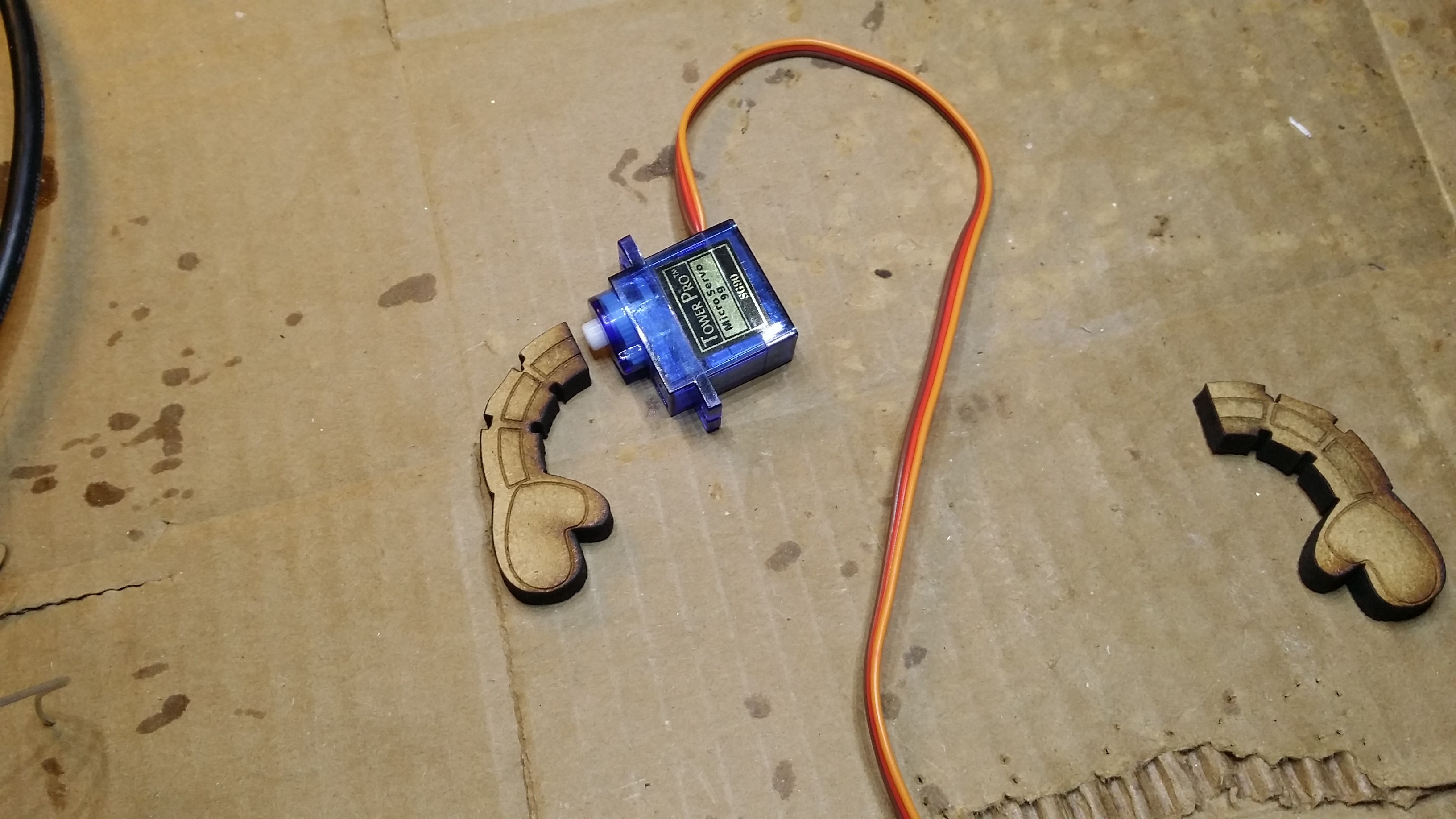
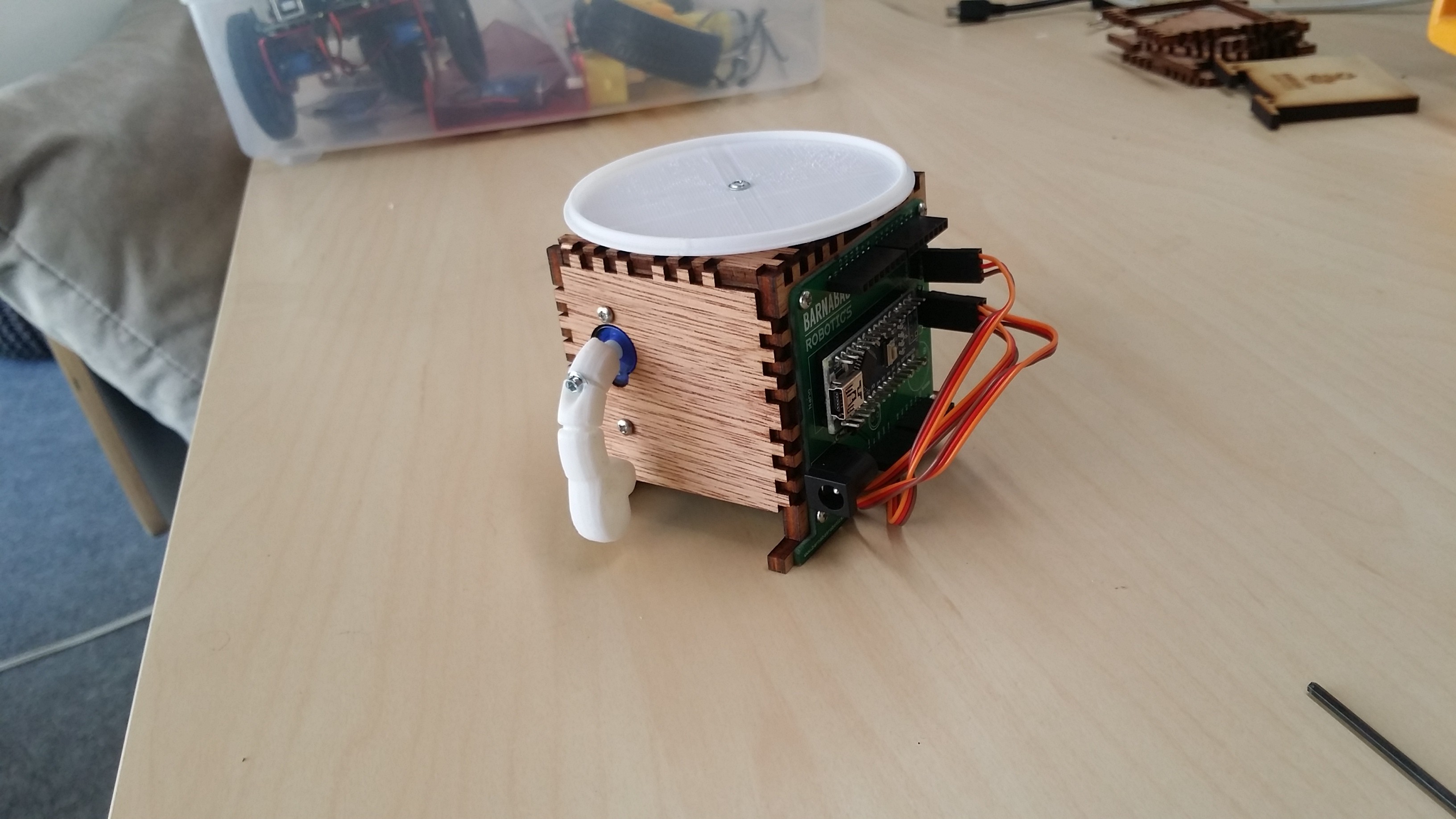
04/15/2017 at 19:58 • 0 commentsThis week we began the process of adding arms to our wooden Barnabas-Bot robot. Our first attempt.. laser cut some arms and a little socket to match the screw.
It's a little loose, but there is hope. We'll continue to tweak the design. More later!
![]()
-
Steady as she goes -Eric
04/08/2017 at 06:04 • 0 commentsHey guys,
Me again, with another project update. Not much has happened since I checked in with you guys last. I've been at work altering the schematic, primarily switching the ATMEGA16U2 with the FT231xS as the serial to USB chip of choice. Possibly more important though is the addition of a few resettable fuses and zener diodes intended to protect the circuit from mistakes that we can expect, and have witnessed, from 10 year olds. Edward is responsible for most of those changes. He pointed them out in the first place.
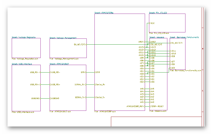
In addition to that I have, with the help of Edward, setup github branch libraries for the future, as I will need to make separate versions for each manufacturer. or now I just have a base branch that I am calling the control branch. Just a bit of a safety net incase I need to hit the rest button. Next step for me is creating a prototype board of each subsystem so that I can test each part of the board piece by piece, rather than constructing it all at once then scratching my head when it doesn't work.
For those who are interested here is the current incarnation of the total board hierarchy;
![]()
Till next time,
-Eric
-
Puzzlebot update -- arms
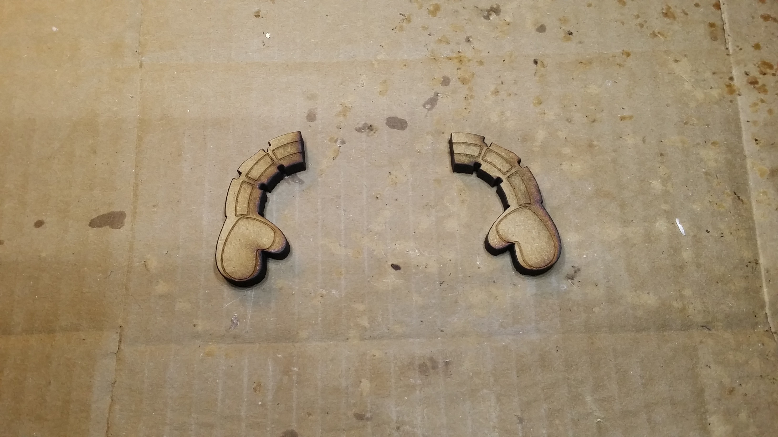
04/08/2017 at 00:06 • 0 commentsCheck out our Barnabas-Bot arms cut from 1/4" MDF! Now to figure out how to attach them to our servos. We'll be playing with a few options this coming week. Our goal is to make it as low cost as possible for someone to fabricate and assemble this robot at home with their child. A few options we are considering:
- Use off-the-shelf servo arm clamps
- Some kind of friction/press fit
- Superglue
We'll let you know what we come up with!
Ed
![]()
![]()
-
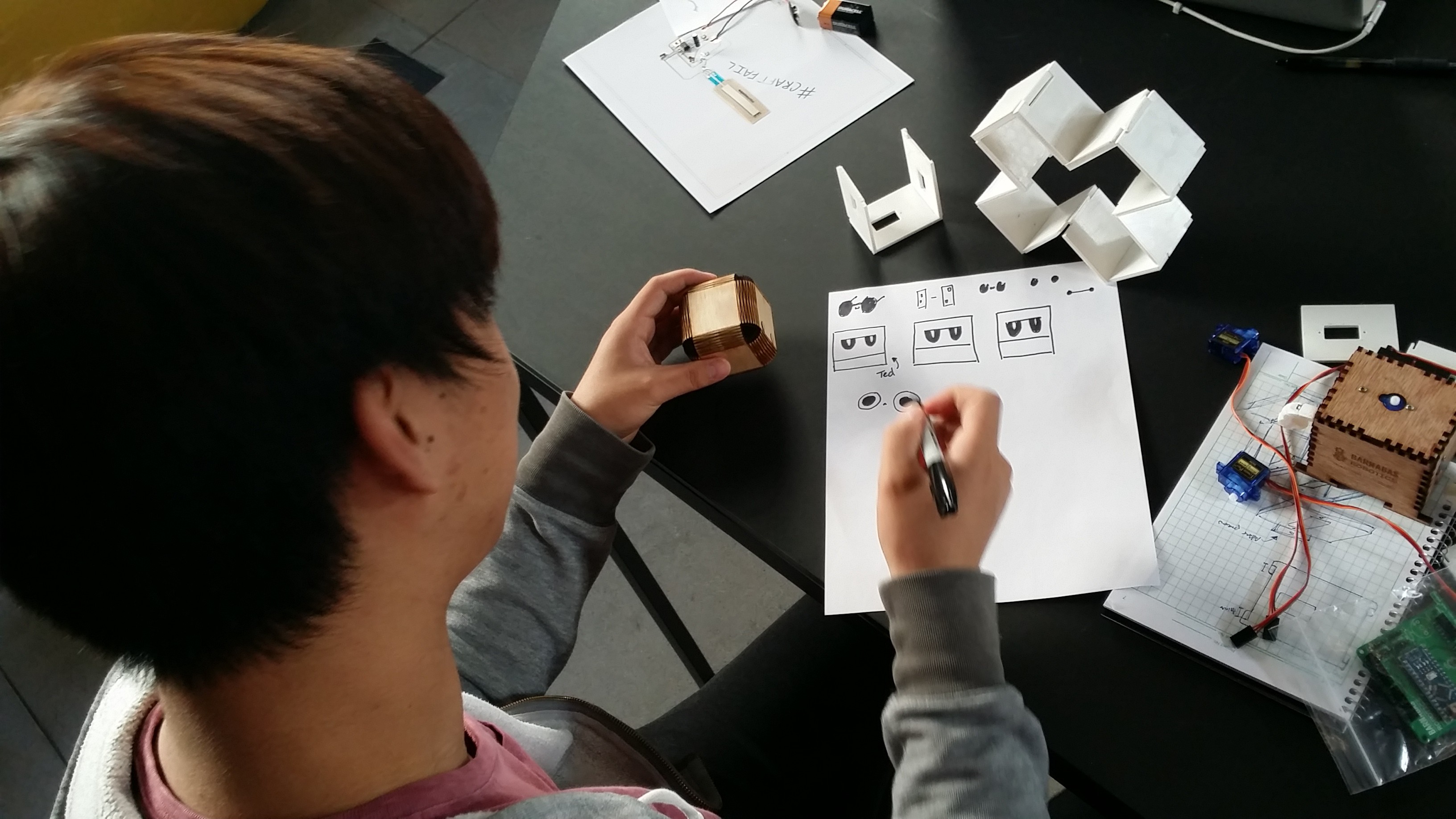
Puzzlebot gets a head!
04/01/2017 at 21:20 • 0 commentsI started to play with some open source designs to make a laser cut head for our wooden robot. A pretty good one at: https://obrary.com/products/laser-cut-cube
I'll continue to experiment and hopefully cut out some arms this week. Until next time!
![]()
![]()
-
Refining the schematic -Eric
04/01/2017 at 02:54 • 0 commentsSo last time I checked in I was just finishing up the noggin schematic, or so I thought. In the time since Dan has given myself and some of the other residents at the Design Lab an in depth presentation on the Uno schematic. There were two things that were immediately obvious to me after that:
- I need a separate voltage regulator for the servo motors. The servo motors draw a lot of current and in junction with the demands of the microcontroller and the rest of the circuit it's just to much current being drawn from one regulator. I have changed the schematic to immediately branch off into two separate voltage regulators. One for the internal circuit, and another to power the servo motors.
- The ATMEGA16U2 needs to go. There are less complicated options for the USB to serial chip, such as the FT231xS that the Sparkfun Redboard uses. There are two big reasons for the change, one being the cost of the 16U2, and the other being the large current it draws from the circuit.
Lastly there is the reset circuit;
![]()
So I am considering what Dan has suggested I do with this circuit and replace it with a reset/supervising IC. I bring this reset circuit up because for the first time in this project I am considering manufacturing concerns in my design. It may turn out that this current circuit is cheaper to manufacture than a circuit that makes use of the fore mentioned IC's, especially when considering house parts. So I need to do some research into the cost of each option.
Till next time
-Eric
-
I'M BACK
03/31/2017 at 17:42 • 0 commentsHello committed followers of the digital age and ...
![]()
In this week's log i will take you all on a journey of my past failures and success since last week. But before i begin, i must add a disclaimer that if you have any allergies with memes, then please stop here.
Now, if you have decided to stay then...
![]()
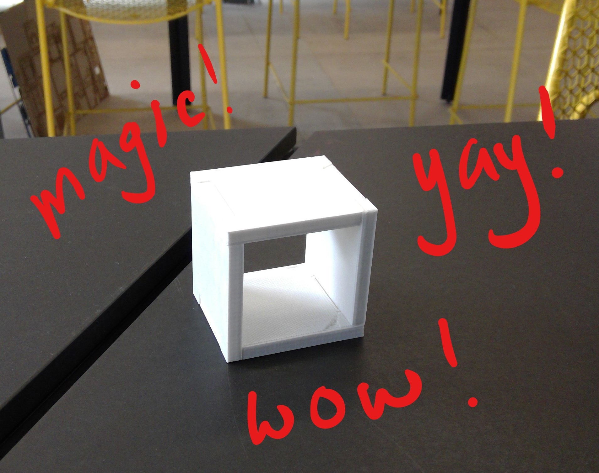
Last time, i was printing a design of interlocking system and let me tell you now, it worked!
But the next issue is that 1/4 of an inch is too thick, so my next design is to make it thinner...![]()
![]()
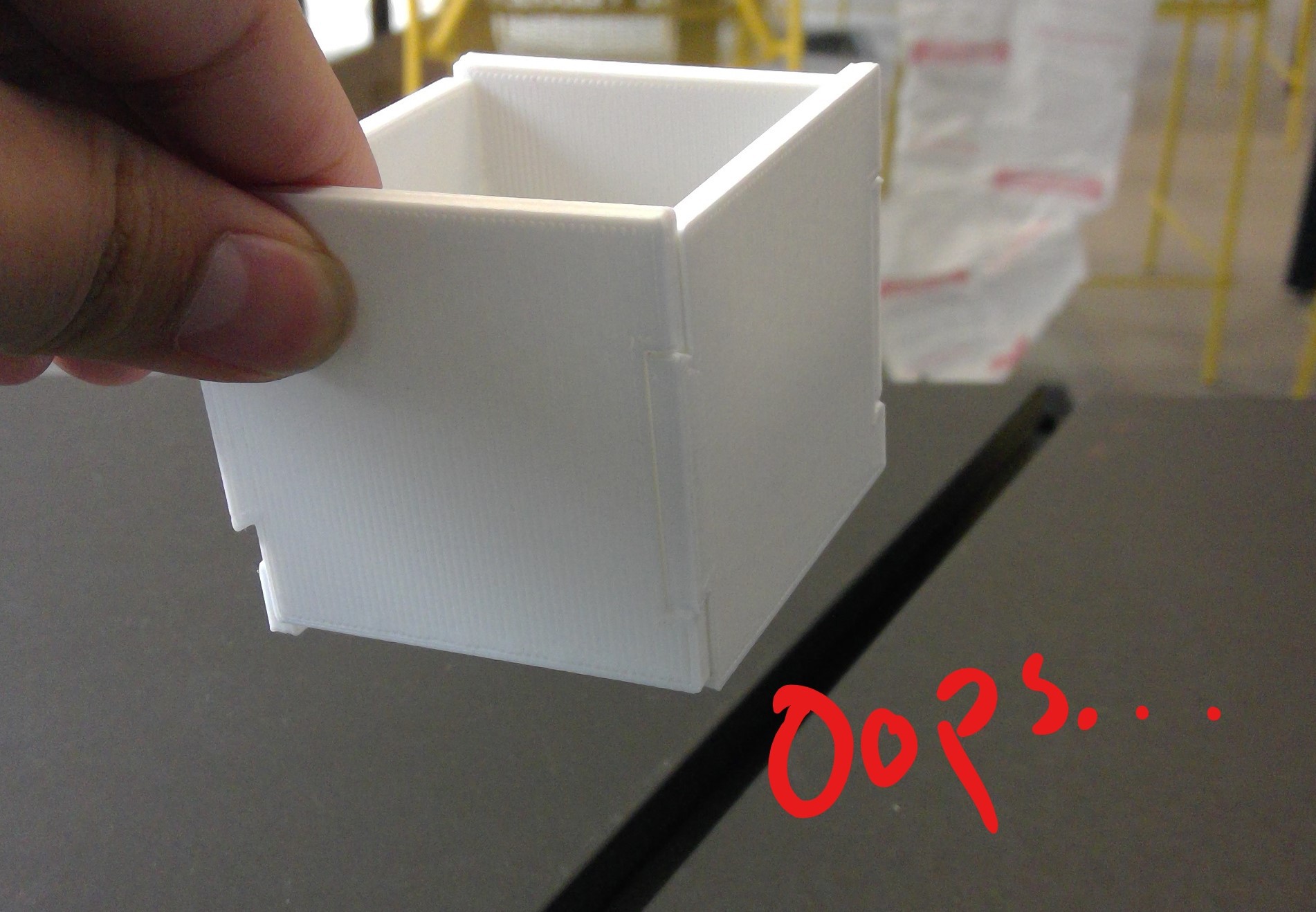
Yes, i know what all of you out there are thinking...
![]()
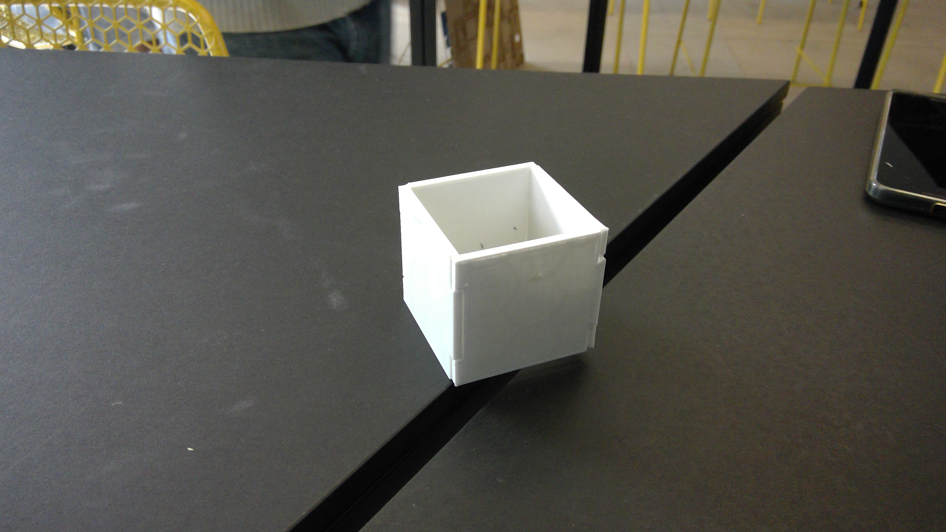
That's right, somehow during the process of making it thinner, i managed to offset the tabs so the box will never close.... ever... but it's alright since mistakes a bound to happen anyways! So off i go to mend my mistakes and hopefully it works this time!
Yes, it does work. Now many of you by now would wonder by "work" what do i mean? I mean that with the same thickness i am able to still have the structural support of external forces being pushed on the cube without it giving out. Now continue, i would like to thank Hunter, another resident in supplyframe, for her help on artistic advice. Her project concept is really cool and you all should check it out. NOW back to the boxes, let me remind you all that in the past few weeks, i had to crunch major time into learning Fusion360 and the next step into the design is actually getting holes to fit into the panes.![]()
And after a long processes of measuring and designing...
![]()
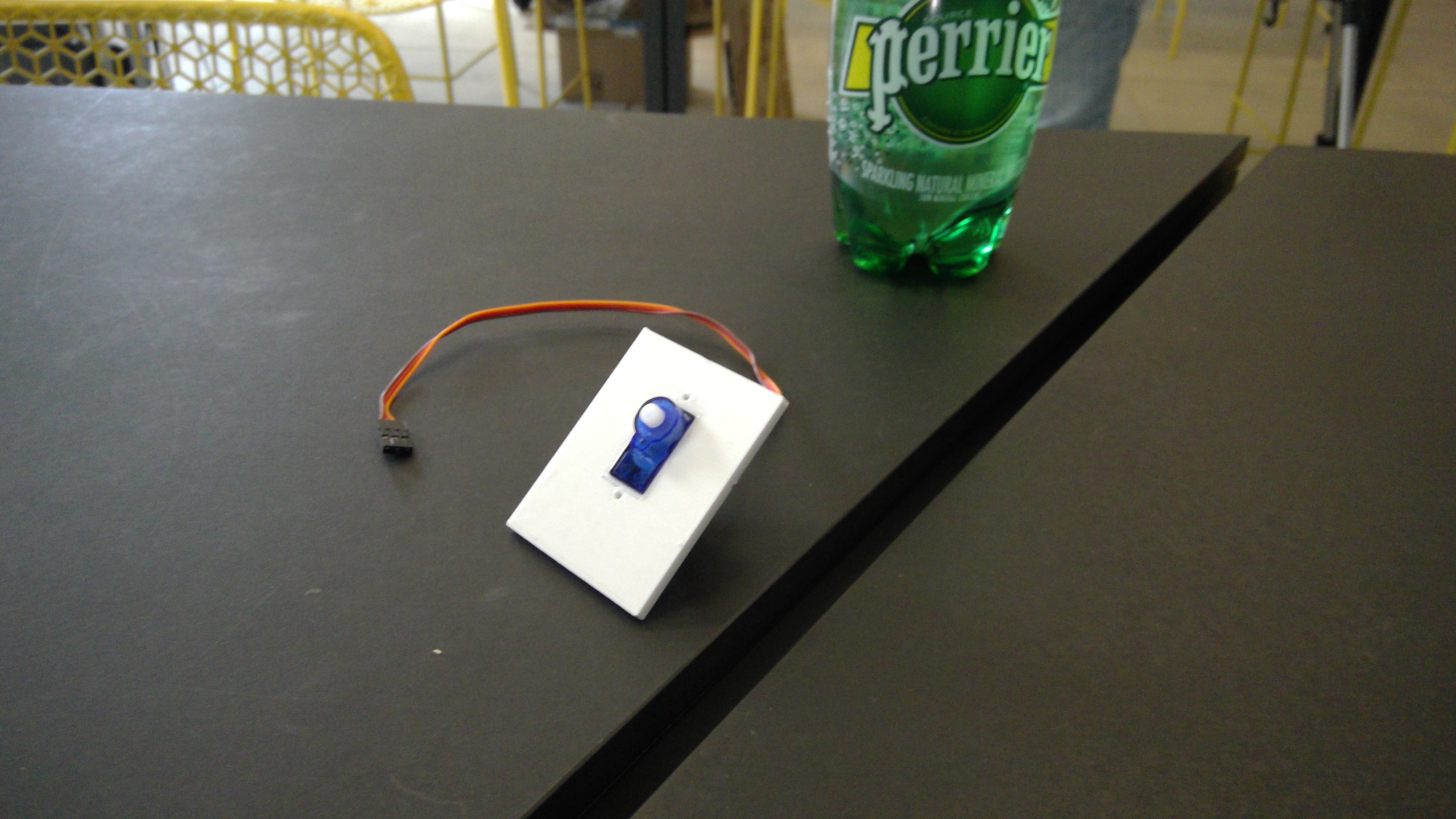
I was able to get the holes to fit perfectly with our servos like so.
![]()
So for now ill leave it here, until next time...
![]()
-Ryan
-
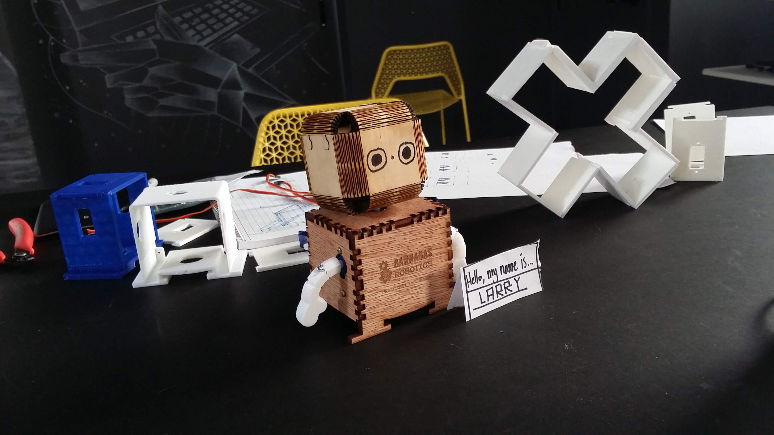
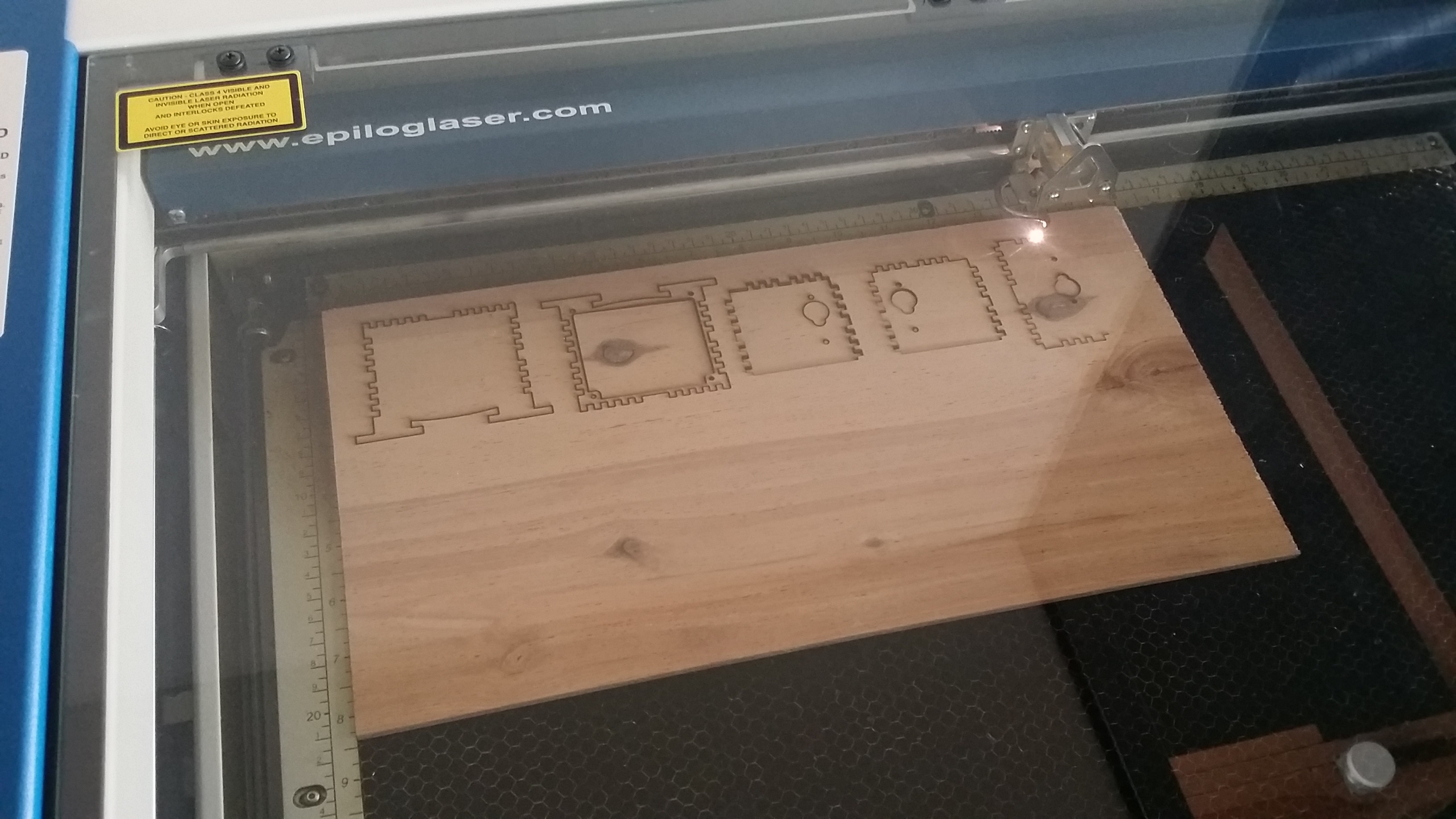
Laser Cut Body - side project
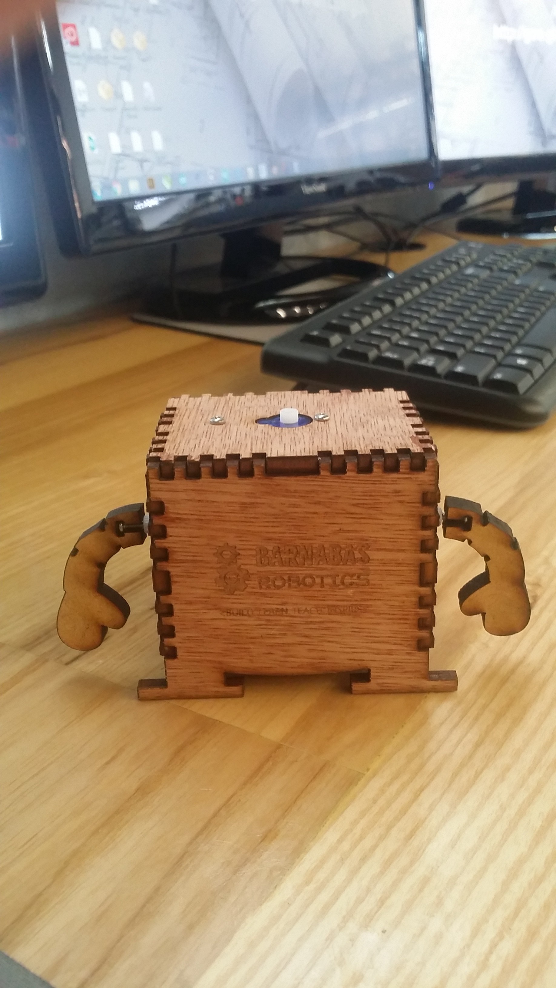
03/25/2017 at 17:59 • 0 commentsWood Barnabas-bot, anyone?
We've always wanted to experiment with fabrication methods outside of 3-D printing. This week we got to try laser cutting him out of plywood. Not bad for a first prototype. Special thanks to Christine Su for submitting the design!
Edit
![]()
![]()
![]()
Barnabas-Bot
An open-source educational robotics project that inspires elementary and middle school kids to invent through building their own robot