 Sagar 001
Radio technology is the best monitoring and control solution for small and long range wireless hobby projects. With other wireless controlling technologies like Buetooth and Wi-Fi AT commands system configuration is required which are very complex and need a setup program. Wifi's signal limitations and high power consumption, IR emission angle and inability to penetrate through the walls limits its use also. So the best low cost, low power alternative is to use RF modules. But RF transmission directly without any encoding scheme does not make any sense. That’s why for this purpose we need a better transmitter and receiver.
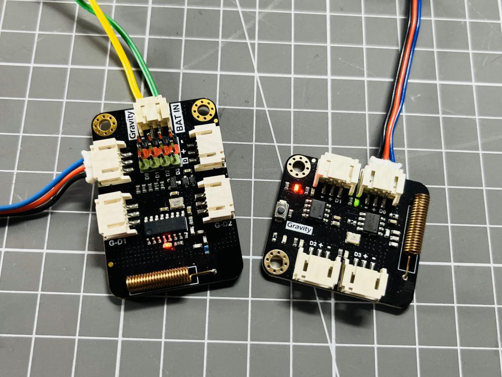
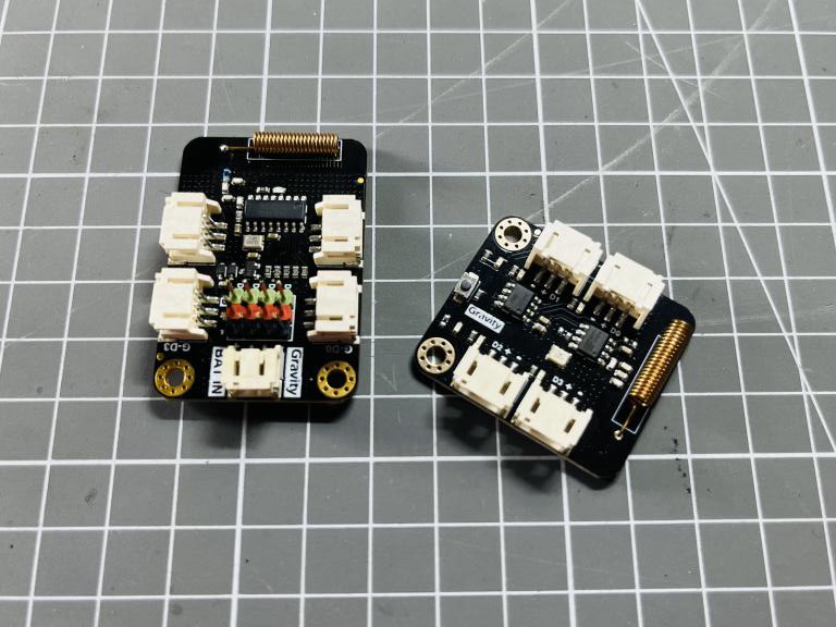
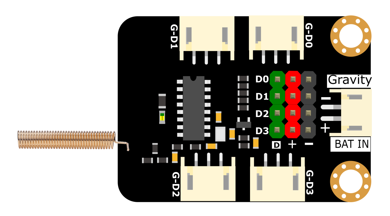
Here is the DFrobot Gravity: Digital Wireless TX-RX pair. Based on 433Mhz RF communication technology, the module includes a transmitter and receiver and features the advantages of simple operation, high scalability, strong penetration, and ultra-low standby power consumption. These modules are used on a wide variety of applications that require wireless control, such as, remote control, wireless doorbell, wireless signal transmission, upgrading wired buttons to wireless buttons, etc.
Basic Design approach:
The module transmitter can be used without connecting to the microcontroller. After connecting the battery, you can directly use the switch button as the "trigger button" for signal transmission. For the code transmission purposes I made a shield using tactile switch buttons.
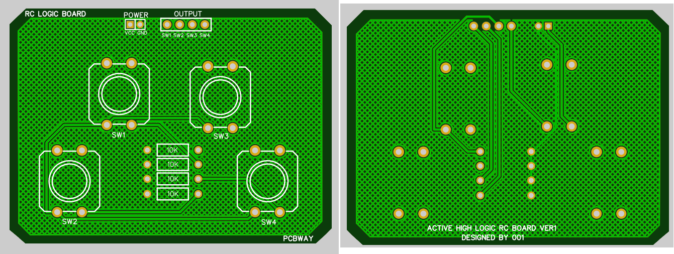
This can be directly connected to the DFrobot transmitter board. This Transmitter receiver system is capable of taking 4 inputs, which makes 15 different combinations. This shield works on an active high logic. I used PCBWay services for making the shield. PCBWay is the best low cost solution for PCB prototyping, PCBA, Stencil, 3D and CNC services. Quote now using this link and get Free PCB coupons on first sign-up. Get 10 Pcs of high quality custom PCBs for just $5.
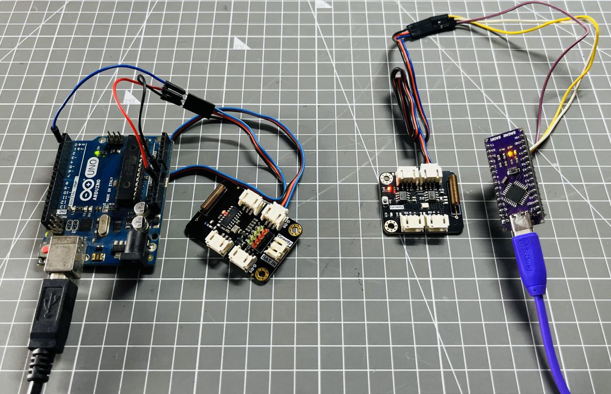
In this tutorial first we have to configure the receiver with the transmitter. Because in RF transmission info can be easily stolen that’s why a otp based encoding scheme is used. To configure the transmitter and receiver I am using a basic approach of blink sketch in which two Arduino boards are required. Then to actually use the TX-RX device I built a remote shield for the transmitter. This time only one Arduino is required, no need of microcontroller for the transmitter unit.
Components Required:
![]() DFrobot Gravity: Digital Wireless TX-Rx pair
DFrobot Gravity: Digital Wireless TX-Rx pair- Remote control shield PCB from PCBWAY
- 5V battery
- Connection wires
- Arduino Microcontroller
Encoding Scheme:
The product adopts the EV1527 encoding format and the four-digit key value code can be combined into 15 different states.The receiver has a corresponding pairing function to ensure that only the paired transmitting device can control the receiver. The receiver supports four working modes: inching, latching, self-locking, and interlocking. It can be paired with EV1527 coded transmitters. One receiver can be paired with up to 32 transmitters. The transmitter and receiver support "one-transmit and multiple-receive" or "one-receive and multiple-transmit" after pairing.
Application:
Wireless door bell
Remote control
Deployed as a sensor signal acquisition node
Wired button upgrade wireless button
Features
- 15 button states of the transmitter
- Pairing function for the receiver
- Support one-transmit and multiple-receive/one-receive and multiple-transmit
- Multiple working modes: inching, latching, self-locking, and interlocking
- Working voltage: 3.3~5.0V DC
- Working frequency: 433Mhz
Paring Method of TX-RX:
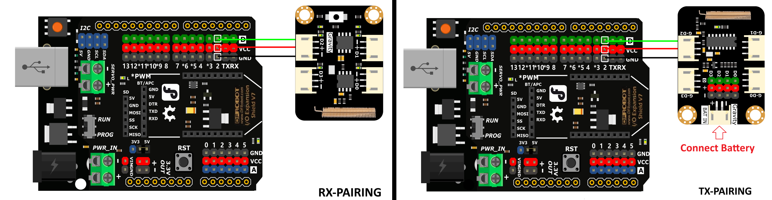
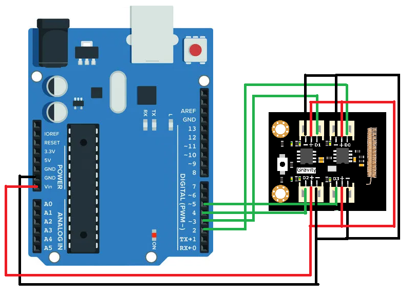
The transmitter and receiver Arduino sketch is given below. Upload the sketch in the Arduino. Connect the transmitter and receiver according to the above given schematics. After powering up the system press and hold the onboard tactile switch of the receiver module for 1.5sec. Wait for 3-4 seconds and keep the transmitter On Blue led will blink twice and stop which is indication of successful pairing.
//Transmitter:
#define Button_D2 2 //Arduino
void setup() {
pinMode(LED_BUILTIN, OUTPUT);
}
void loop() {
digitalWrite(Button_D2, HIGH);
delay(1000);
digitalWrite(Button_D2, LOW);
delay(1000);
}
//////////////////////////////////////////////////////////////////////////////
//Receiver:
#define Button_D2 2 //Arduino
void setup() {
Serial.begin(115200);
pinMode(Button_D2, INPUT);
}
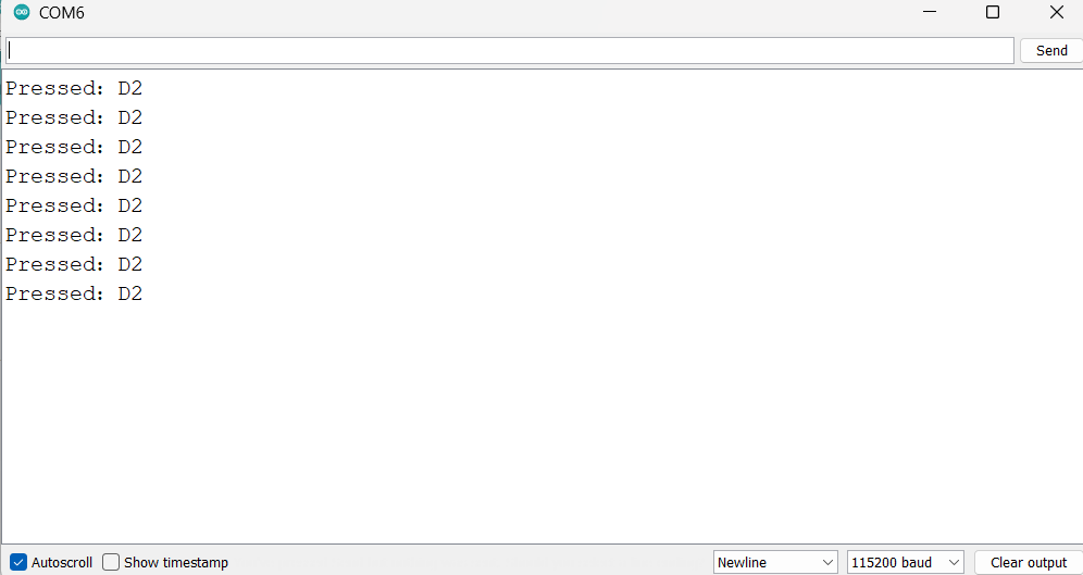
void loop() {
if (digitalRead(Button_D2)) {
Serial.println("Pressed:D2");
delay(1000);
}
}
Connection:
Paring:
Successful:
Clear pairing:
The receiver can store up to 32 sets of transmitter codes. When there are more than 32 sets, the first paired code will be overwritten; Clear all paired transmitters: Press and hold the button on the receiving end for more than 4 seconds. After releasing your hand, the blue indicator light flashes twice to successfully clear all paired transmitters; if the clearing fails, repeat the above operation.
Example project for TX-RX unit:
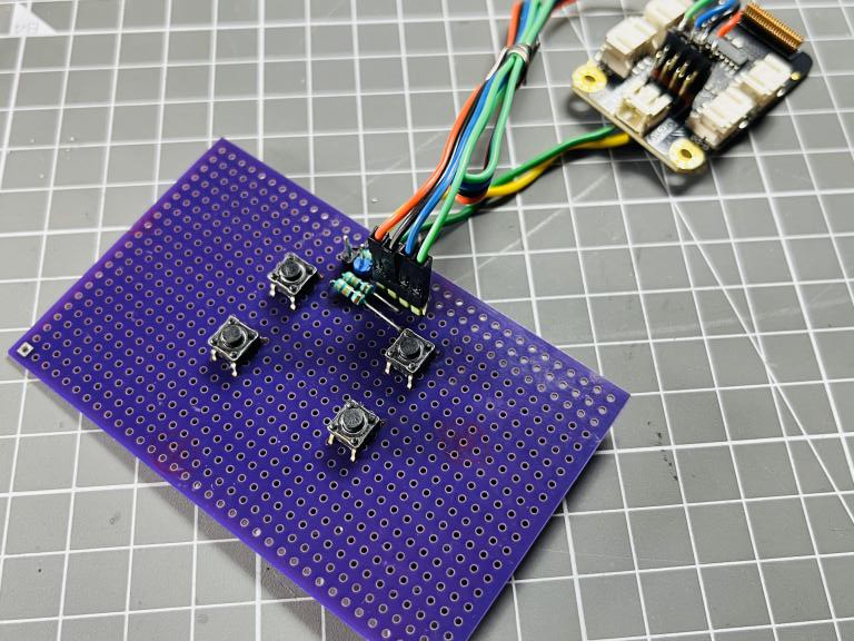
Transmitter: I made this shield using the above given schematics, the transmitter does not need any microcontroller interface but a remote control shield which is made using PCBWay PCB prototyping service. The above shield is similar to the below one, Download all the required data and Gerber files for this project from here.
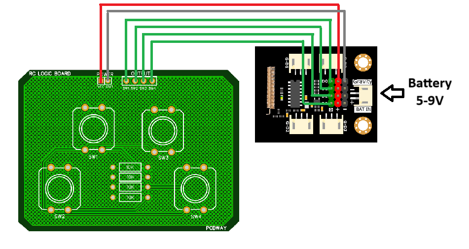
The shield has 4 tactile switches for 4 channels for the receiver. Four outputs for the digital channel and 2 power inputs which make the shield to use in active high mode. Check the schematics and connection diagram with the shield.
Receiver: The receiver needs an arduino for the interpretation of transmitted code. And then to control the respective digital pins to control any peripherals attached to it. The connection diagram of the receiver with the Arduino is given above.
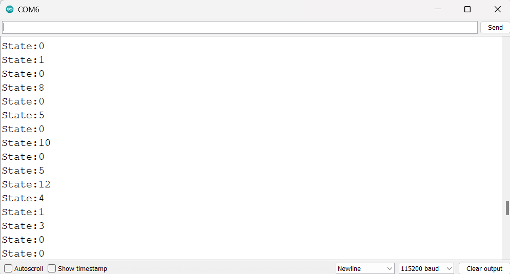
In the below given sketch D2 to D5 of Arduino is used as input port and D6 to D9 are digital controlled output. These 4 outputs can be used to control any external device. By default the Onboard led’s on the receiver boards are controlled with them. Whenever the buttons on the transmitter shield are pressed the respective output on the receiver board is pulled up. Hence we can wirelessly control the devices.
To control any other device like DC motors, heavy load, A PWM based controller can be used which acts as a middle unit. Receive the signals from the RX board and give the respective output of the DC motor.
Code for Receiver:
#define Button_D2 2//Arduino
#define Button_D3 3//Arduino
#define Button_D4 4//Arduino
#define Button_D5 5//Arduino

void setup() {
  Serial.begin(115200);
  pinMode(Button_D2, INPUT);
  pinMode(Button_D3, INPUT);
  pinMode(Button_D4, INPUT);
  pinMode(Button_D5, INPUT);
  pinMode(6, OUTPUT);
  pinMode(7, OUTPUT);
  pinMode(8, OUTPUT);
  pinMode(9, OUTPUT);
}
void loop() {
  if (((digitalRead(Button_D5)==0) && (digitalRead(Button_D4)==0) && (digitalRead(Button_D3)==0)&& (digitalRead(Button_D2)==0))) {
    Serial.println("State:0");
    digitalWrite(6, LOW);
    digitalWrite(7, LOW);
    digitalWrite(8, LOW);
    digitalWrite(9, LOW);
    delay(500);
  }
    if (((digitalRead(Button_D5)==0) && (digitalRead(Button_D4)==0) && (digitalRead(Button_D3)==0)&& (digitalRead(Button_D2)==1))) {
    Serial.println("State:1");
    digitalWrite(6, HIGH);
    digitalWrite(7, LOW);
    digitalWrite(8, LOW);
    digitalWrite(9, LOW);
    delay(500);
  }
    if (((digitalRead(Button_D5)==0) && (digitalRead(Button_D4)==0) && (digitalRead(Button_D3)==1)&& (digitalRead(Button_D2)==0))) {
    Serial.println("State:2");
    digitalWrite(6, LOW);
    digitalWrite(7, HIGH);
    digitalWrite(8, LOW);
    digitalWrite(9, LOW);
    delay(500);
  }
     if (((digitalRead(Button_D5)==0) && (digitalRead(Button_D4)==1) && (digitalRead(Button_D3)==0)&& (digitalRead(Button_D2)==0))) {
    Serial.println("State:4");
    digitalWrite(6, LOW);
    digitalWrite(7, LOW);
    digitalWrite(8, HIGH);
    digitalWrite(9, LOW);
    delay(500);
  }
    if (((digitalRead(Button_D5)==1) && (digitalRead(Button_D4)==0) && (digitalRead(Button_D3)==0)&& (digitalRead(Button_D2)==0))) {
    Serial.println("State:8");
    digitalWrite(6, LOW);
    digitalWrite(7, LOW);
    digitalWrite(8, LOW);
    digitalWrite(9, HIGH);
    delay(500);
  }
    if (((digitalRead(Button_D5)==0) && (digitalRead(Button_D4)==0) && (digitalRead(Button_D3)==1)&& (digitalRead(Button_D2)==1))) {
    Serial.println("State:3");
    digitalWrite(6, HIGH);
    digitalWrite(7, HIGH);
    digitalWrite(8, LOW);
    digitalWrite(9, LOW);
    delay(500);
  }
     if (((digitalRead(Button_D5)==0) && (digitalRead(Button_D4)==1) && (digitalRead(Button_D3)==0)&& (digitalRead(Button_D2)==1))) {
    Serial.println("State:5");
    digitalWrite(6, HIGH);
    digitalWrite(7, LOW);
    digitalWrite(8, HIGH);
    digitalWrite(9, LOW);
    delay(500);
     }
    if (((digitalRead(Button_D5)==0) && (digitalRead(Button_D4)==1) && (digitalRead(Button_D3)==1)&& (digitalRead(Button_D2)==0))) {
    Serial.println("State:6");
    digitalWrite(6, LOW);
    digitalWrite(7, HIGH);
    digitalWrite(8, HIGH);
    digitalWrite(9, LOW);
    delay(500);
     }
    if (((digitalRead(Button_D5)==0) && (digitalRead(Button_D4)==1) && (digitalRead(Button_D3)==1)&& (digitalRead(Button_D2)==1))) {
    Serial.println("State:7");
    digitalWrite(6, HIGH);
    digitalWrite(7, HIGH);
    digitalWrite(8, HIGH);
    digitalWrite(9, LOW);
    delay(500);
     }
    if (((digitalRead(Button_D5)==1) && (digitalRead(Button_D4)==0) && (digitalRead(Button_D3)==0)&& (digitalRead(Button_D2)==1))) {
    Serial.println("State:9");
    digitalWrite(6, HIGH);
    digitalWrite(7, LOW);
    digitalWrite(8, LOW);
    digitalWrite(9, HIGH);
    delay(500);
     }
    if (((digitalRead(Button_D5)==1) && (digitalRead(Button_D4)==0) && (digitalRead(Button_D3)==1)&& (digitalRead(Button_D2)==0))) {
    Serial.println("State:10");
    digitalWrite(6, LOW);
    digitalWrite(7, HIGH);
    digitalWrite(8, LOW);
    digitalWrite(9, HIGH);
    delay(500);
     }
    if (((digitalRead(Button_D5)==1) && (digitalRead(Button_D4)==0) && (digitalRead(Button_D3)==1)&& (digitalRead(Button_D2)==1))) {
    Serial.println("State:11");
    digitalWrite(6, HIGH);
    digitalWrite(7, HIGH);
    digitalWrite(8, LOW);
    digitalWrite(9, HIGH);
    delay(500);
     }
    if (((digitalRead(Button_D5)==1) && (digitalRead(Button_D4)==1) && (digitalRead(Button_D3)==0)&& (digitalRead(Button_D2)==0))) {
    Serial.println("State:12");
    digitalWrite(6, LOW);
    digitalWrite(7, LOW);
    digitalWrite(8, HIGH);
    digitalWrite(9, HIGH);
    delay(500);
     }

     if (((digitalRead(Button_D5)==1) && (digitalRead(Button_D4)==1) && (digitalRead(Button_D3)==0)&& (digitalRead(Button_D2)==1))) {
    Serial.println("State:13");
    digitalWrite(6, HIGH);
    digitalWrite(7, LOW);
    digitalWrite(8, HIGH);
    digitalWrite(9, HIGH);
    delay(500);
     }
     if (((digitalRead(Button_D5)==1) && (digitalRead(Button_D4)==1) && (digitalRead(Button_D3)==1)&& (digitalRead(Button_D2)==0))) {
    Serial.println("State:14");
    digitalWrite(6, LOW);
    digitalWrite(7, HIGH);
    digitalWrite(8, HIGH);
    digitalWrite(9, HIGH);
    delay(500);
     }
    if (((digitalRead(Button_D5)==1) && (digitalRead(Button_D4)==1) && (digitalRead(Button_D3)==1)&& (digitalRead(Button_D2)==1))) {
    Serial.println("State:15");
    digitalWrite(6, HIGH);
    digitalWrite(7, HIGH);
    digitalWrite(8, HIGH);
    digitalWrite(9, HIGH);
    delay(500);
     }

  delay(100);
}
Mode switch:
The receiver is in inching mode by default, the following examples all take inching mode as an example. If there is no requirement for using other modes, you can skip this step. In the above example I used the receiver in Inching mode, which is default mode.
Inching: After D0 receives the signal once, it stays high until D1~D3 receive the signal
Latching: Each time D0 receives a signal, the corresponding output state is inverted once, the same is true for D1 to D3
Self-locking: D0 receives the signal and outputs high level, but does not receive the signal low, the same is true for D1 to D3
Interlocking: When receiving the signal D0, D0 stays at a high level, and all the others are low. The same applies to D1 to D3.
Press and hold the button for 0.5 to 1.5 seconds, then release it, the blue indicator light flashes twice, indicating that you have entered the mode switching state, and then you can enter different modes according to the different times of pressing the button within 6 seconds:
Press once to enter the latching mode.
Press twice to enter the self-locking mode.
Press 3 times to enter the inching mode.
Press 4 times to enter the interlocking mode.
According to the mode you need to enter, press the button for the corresponding number of times, and then hold the button for 0.5 to 1.5 seconds as a confirmation signal. After letting go, the blue indicator light flashes 2 times to set successfully and enter the corresponding working mode. 0.5-1.5 seconds is relatively short, be careful not to press overtime.
Distance Test:
The transmitter is connected to a 3.7V lithium battery. Receiver connects to UNO controller 5V power supply. Try to keep the transceiver module at the same height, about 0.5Meter above the ground. The antenna stays in the default position. There is no great attenuation after the signal passes through the wall, and the transmission distance is reduced by about 0.5M each time it passes through the wall.

If the transmitter antenna is re-welded to the state shown in the figure below, the signal transmission distance can be increased to about 25 Meter (if there is no strong welding ability, and the long transmission distance is not required, it is not recommended to re-weld the antenna, because of this state The lower antenna is easily bent and damaged). The total distance measured in the plane's open area is around 500 Metres. Checkout your custom made PCBs now and get best prices on PCBWAY. Sign-up now and get free coupons for PCBs, 10pcs of 2layer board in just $5.