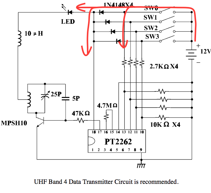
The remote module hacked in this design operates using 12v battery, which is connected to one of the data and Vcc inputs on the PT2262 / AD2262 modulator chip.
This means, the switch should be switching the high side and a simple switch based on a single n-channel MOSFET wouldn't do. And neither would work a p-channel, as the gate can be brought up only to 3.3v level, whereas source voltage would be 12v. A two-MOSFET switch is the solution.
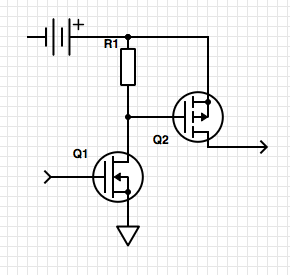
12v battery provides power for p-channel Q2, which performs power switching and also brings Q2 gate up to 12v when Q1 is closed (logical "1"/3.3v on the input) via a pull-up resistor R1. Any fairly high value such as 10k would work. When the input changes to logical "0", Q1 will open, shorting Q2 gate to the ground and switching the 12v output off.
One extra part, important for correct function of the circuit is not shown on the diagram. In a general case Q1 should also have a pull resistor to control gate input voltage in the unknown state. However because input connects to Raspberry Pi, its internal circuitry is expected to drive it low or high explicitly.
This could potentially cause a floating input problem triggering random switching when 12v battery is connected and Raspberry Pi is switched off, however in this project we will find a way to supply 12v from RPi 5v rail using a DC-DC converter, eliminating need for a battery and eliminating the case when 12v might be present when RPi is turned off.
A low-current signal MOSFET can be used as Q1 as it is merely switching Q2 pull-up off. Q2 has to supply entire load. Original data sheets do not provide power consumption ratings neither for the chip itself or a circuit. However, suggested power switch diode 1N4148 is a hint. Its top peak current is 2A and maximum continuous current is 300mA. In practical terms maximum theoretically possible current is determined by internal resistance of the 12v supply.
Generic A23 12v battery data sheet claims that "typical closed circuit voltage no less than 10.4 volts on a
load of 800 ohms at 21oC (70oF) for 0.10 to 2.0 seconds." This is roughly equivalent to 120 ohm internal resistance, or 100mA continuous short circuit current. Consistent with the diode ratings suggested in the data sheet. Therefore power switching p-channel MOSFET Q2 should have a similar rating.
Schematics above can be used to switch any high voltage - high power load (as long as the voltage is safe to switch without isolation) using any logic-level input such as in Raspberry Pi, Arduino, etc.
Discussions
Become a Hackaday.io Member
Create an account to leave a comment. Already have an account? Log In.