 Chris Johnson
For some reason, EC probes are relatively expensive. In most cases they are more expensive than pH probes, which to me seem a lot harder to make. So, I decided to make my own EC probe, as you can see below:
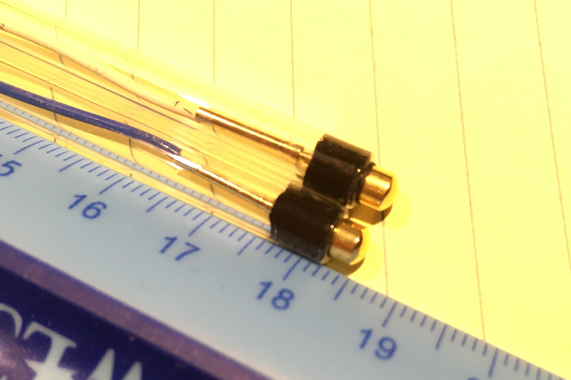
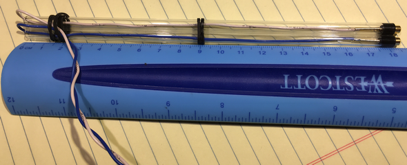
The contacts are gold plated Studex ear piercing studs, which are made in the USA and only about $1 each. Gold is good for EC probes because it does not tarnish. The studs are pushed through a piece of 4mm O-Ring cord to waterproof the electrical contacts. The tubing is 6mm OD x 4mm ID flint glass, which is about $0.25/ft if you buy a 1 pound pack. It is very easy to snap to length. Here is a great video about how to cut and fire polish glass tubing. I would recommend a triangle diamond needle file for scribing. I got this set at Amazon and they worked fine. So, for less than $5 worth of parts (ignoring shipping, tools, and unused material), I was able to make an EC probe.
I had previously verified that the Spiroboard EC circuit could correctly measure the calibration resistors that can be switched in to the circuit under control of the Raspberry PI. By doing a best fit line to the calibration resistors, the circuit could also measure a random resistor plugged onto the EC input to within about 0.5%. So, I though there would be no problem getting the circuit to measure the EC of a real solution.
This is where the "not EC" part comes in. Every EC probe has a K constant that is based on the geometry of the probe contacts. For simple probe geometries it can be calculated. You can also work backwards from measuring several known conductivity solutions to calculate the K factor. This is what I attempted to do for my DIY EC probe, unsuccessfully.
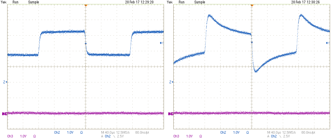
After a lot of poking around and wiping up spilled calibration solutions, I found the problem. The scope screenshots below show the input to the AC-to-DC portion of the EC circuit when measuring a resistor (left) versus measuring an actual solution through the EC probe (right, but unfortunately wrong). The peaking is caused by the capacitance of the EC probe and the solution. The peaking breaks the linear relation between resistance and the output of the AC-to-DC circuit. The original circuit that I based this on used a sinusoidal oscillator. My assumption is that it does not have a similar problem because the relatively slow rise of the sine wave masks the peaking effect. Bottom line, the EC circuit as designed can not accurately measure the EC for real solutions.
But, all is not lost. A solution (pun intended), is to dispense with the AC-to-DC circuit entirely and just directly measure the DC voltage after the peaking has settled out. I successfully Spice simulated a circuit modification and now need to figure out the best way to patch the board to support it. Since the ADC now directly measures the output of the EC amplifier, this method could potentially be more accurate than the AC-to-DC version.
Discussions
Become a Hackaday.io Member
Create an account to leave a comment. Already have an account? Log In.