 M.daSilva
 So, next step is redrawing every circuit on individual PCBs, while trying to make them as "flexible" as possible, ie allow some headroom for some later mods.
Now, this is the part where I start looking at other versions of this transceiver and accommodate for the differences there may be between designs. I'll take a look at the Minima (Mk. 3) and the Bitx20, the 14MHz version of the Bitx40.
In order to make the modules "breadboard-friendly", all the headers are .1" and are grid-snapped.
The modules are gonna be as small as possible... I'd like to fit them in a 10x10cm panel! SMD will be extensively used throughout the design. 0805's aren't that hard to hand-solder once you get the hang of it :)
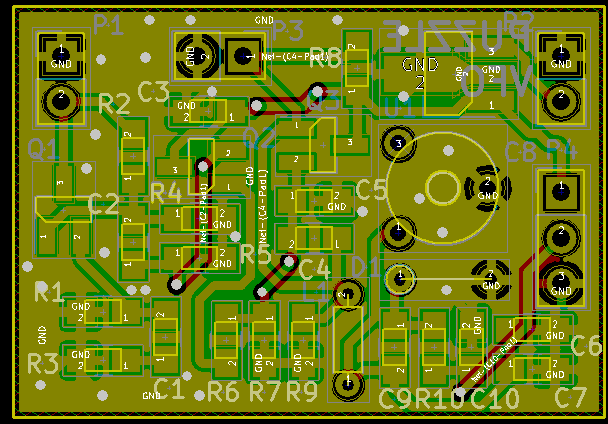
AFAmps
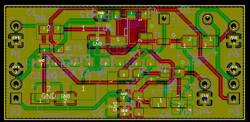
Nothing extremely complex here, a transistor preamp coupled with a LM386 audio amp are used for the speakers, and three other transistors are used for the mic amp. Speaker amp is on one side of the board, while the mic amp is on the other side.
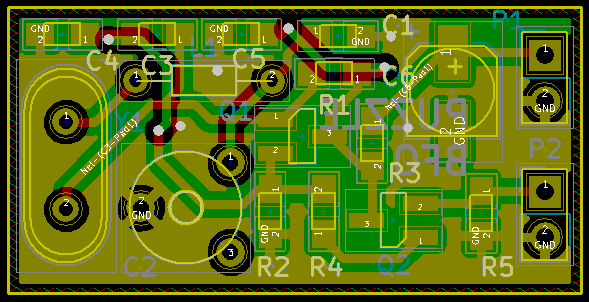
BiDirAmp
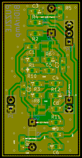
RF and IF amps. I took more care here and kept everything single-sided. I tried some "via stitching" (which BTW is a pain in KiCAD) to keep the parasitic capacitance to a minimum. No idea if it's really significant at those frequencies (I'm more used to seeing that kind of thing in 100MHz and above rigs), guess it can't hurt doing it... Or can it? I could try doing a via-less design and another with vias, and compare the two!
The input and output caps have to be set in accordance with the amp's position in the transceiver.
QuartzBP
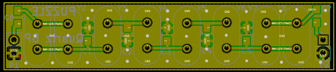
Depending on the designs, there may be 4, 8 crystals, with or without caps in series. This board takes that into account. Building a 4-crystal filter? Short the two outermost crystal footprints! Same goes for the caps.
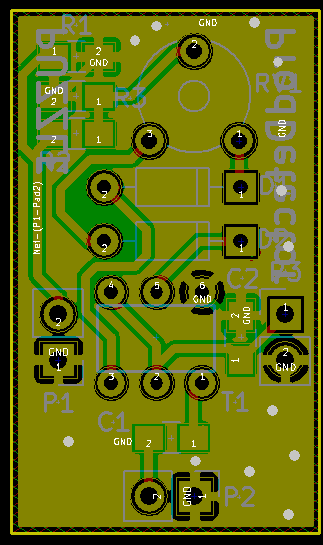
Mixer
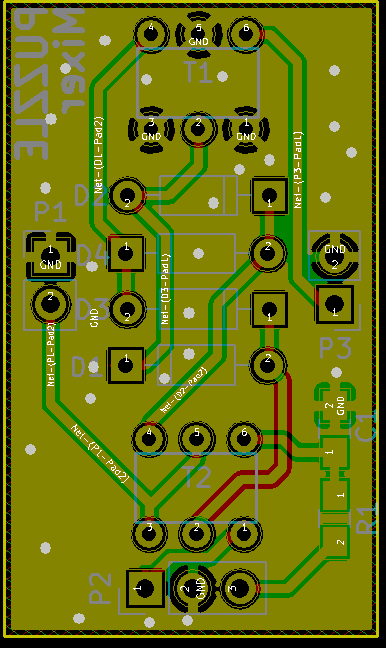
That one was a mind-twister. Transformers always bugged me; I'm not always sure I'm connecting the correct windings, whether they're wound in the correct direction, ... I checked this at least 7 times with hand schematics to make sure every tap was going to the right pin in the footprint. Kept Farhan's idea of using a DIP-6 footprint, compact enough! A FT37-43 core with a trifilar winding should fit right in!
Some personal fail here: one of the traces had to go to the bottom layer of the PCB :( perks of using somewhat thick traces...
ProdDetector
Same thing here; even though Farhan doesn't use a trimpot to balance the mixer on the kits anymore (as a double diode is directly installed), I'd like to keep this possibility.
VFO
Fail again, three bottom layer traces :( . To my defense the board was getting pretty crowded! I don't think I'm gonna use the complete VCO, a DDS will most likely be directly connected to this, using the VFO as a buffer amp.
BFO
That's the last one for today. Pretty versatile design, although I will add a USB/LSB switch (with a second variable cap) in the next version. Let's keep things simple for now!
Still to be done: the Band-Pass filter and the PA, the latter being a bit more challenging...
Discussions
Become a Hackaday.io Member
Create an account to leave a comment. Already have an account? Log In.