 Nelson Phillips
Without going into to many details about how I came to the dimensions because to logic was crude and was mostly governed by the size of the vac and flex hose available.
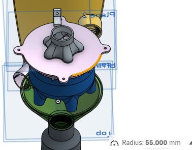
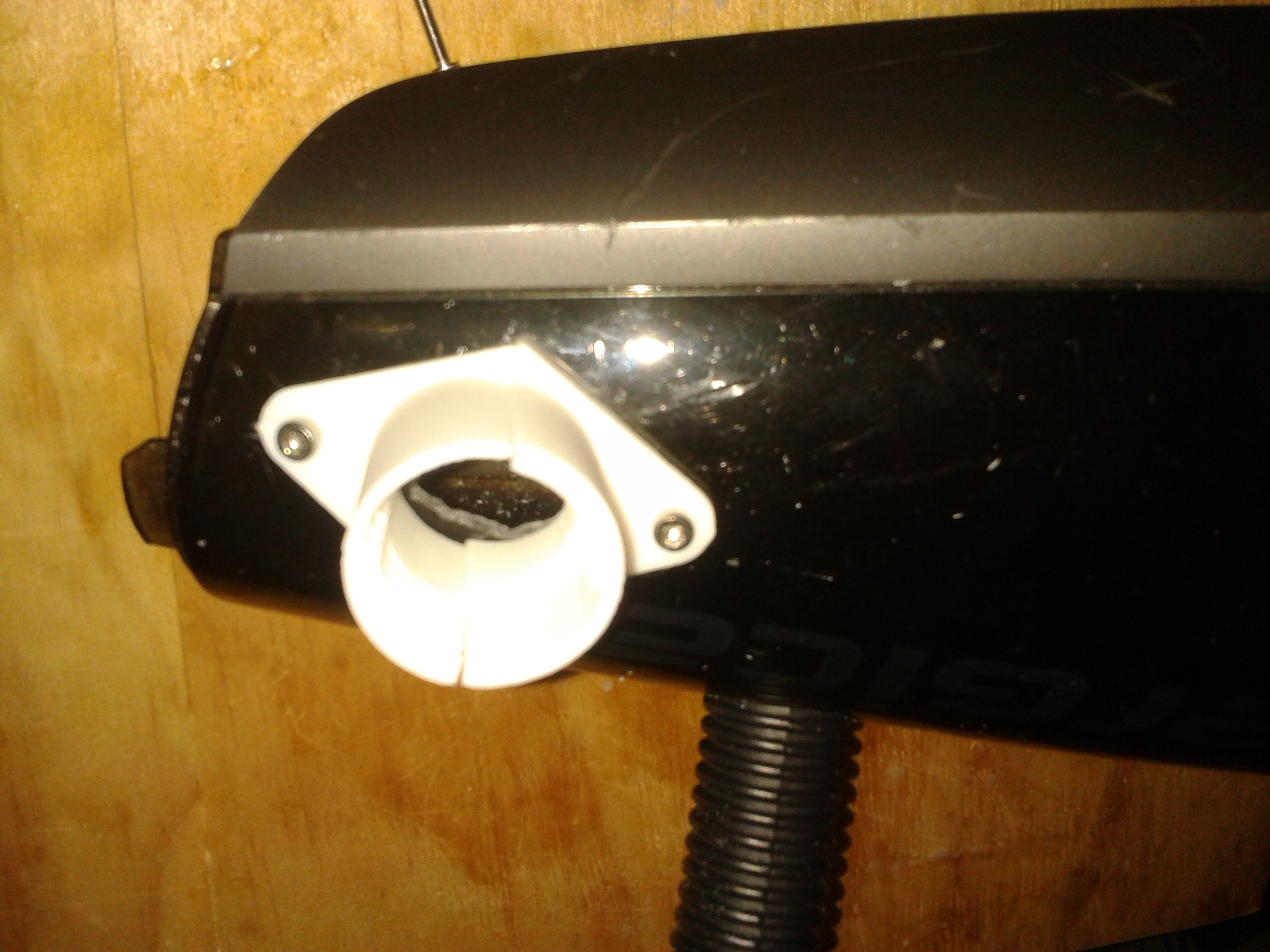
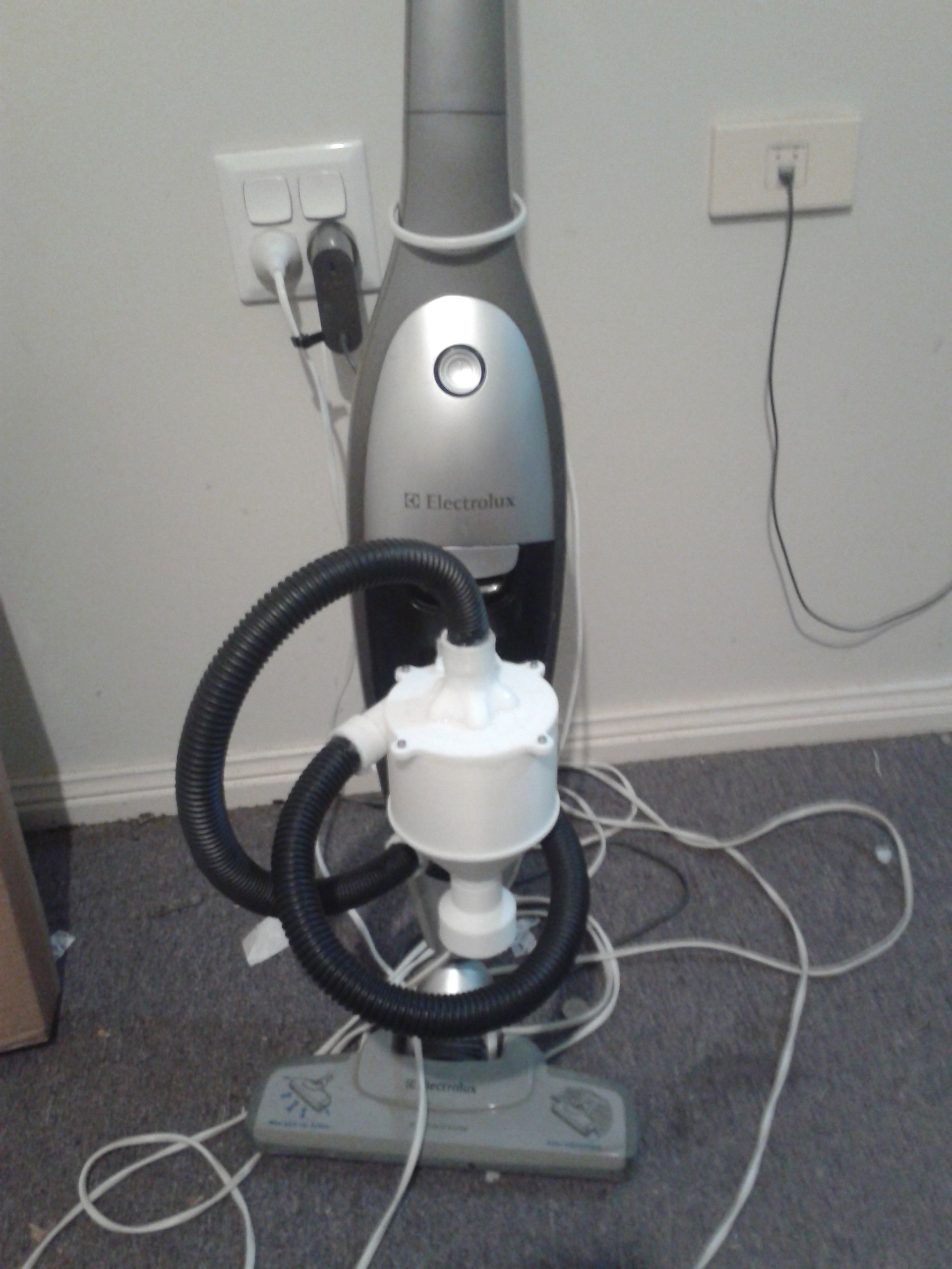
This give a rough guide as to size of the body, the hose was limited as the common flex vacuum hose was just a bit to big. Searching I came across so 22mm outdoor water hose, not ideal but it would work in the constraints of the vacuums camber. The image below shows the original idea of a bracket interfacing with the chamber inlet, but it also shows the space constraint.
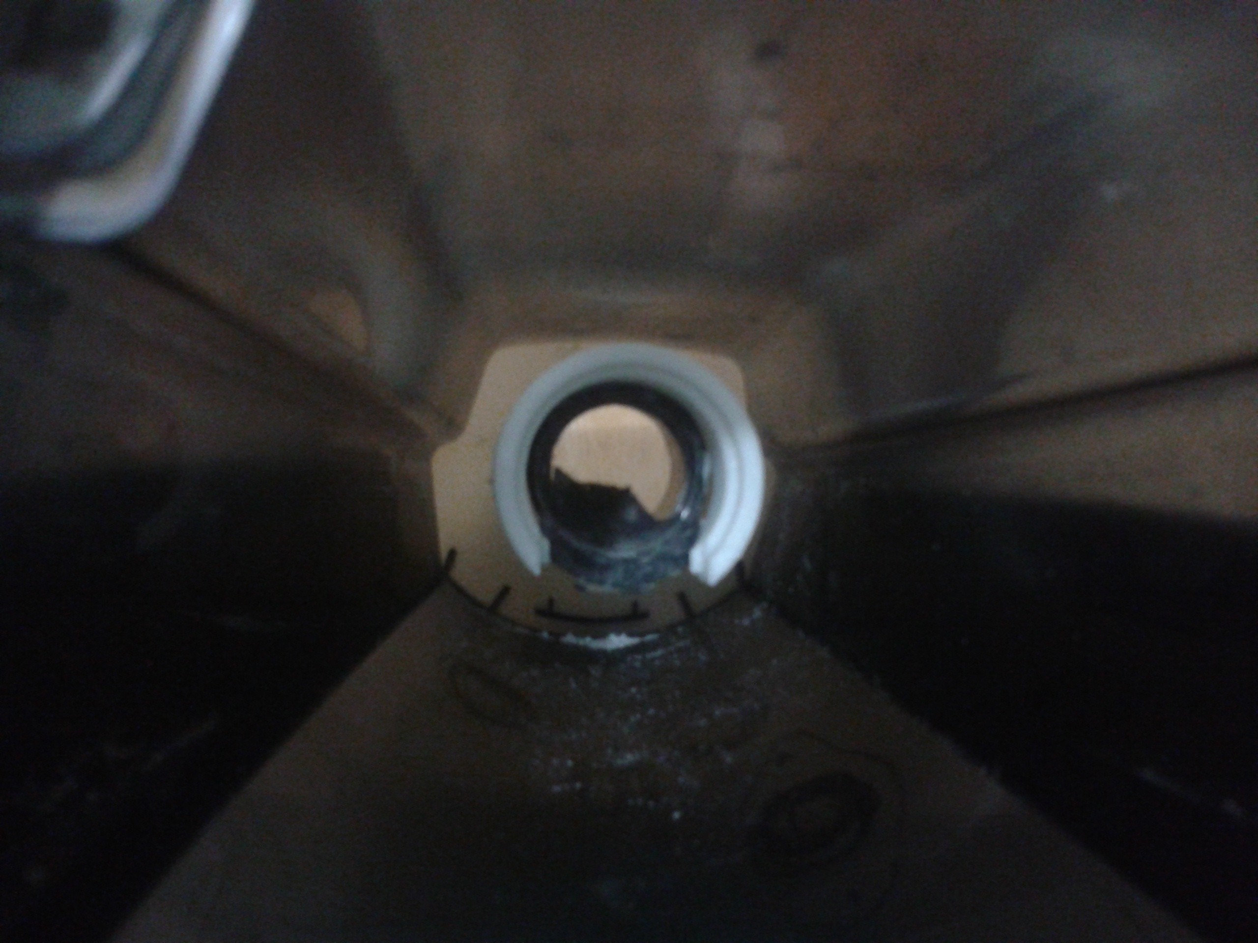
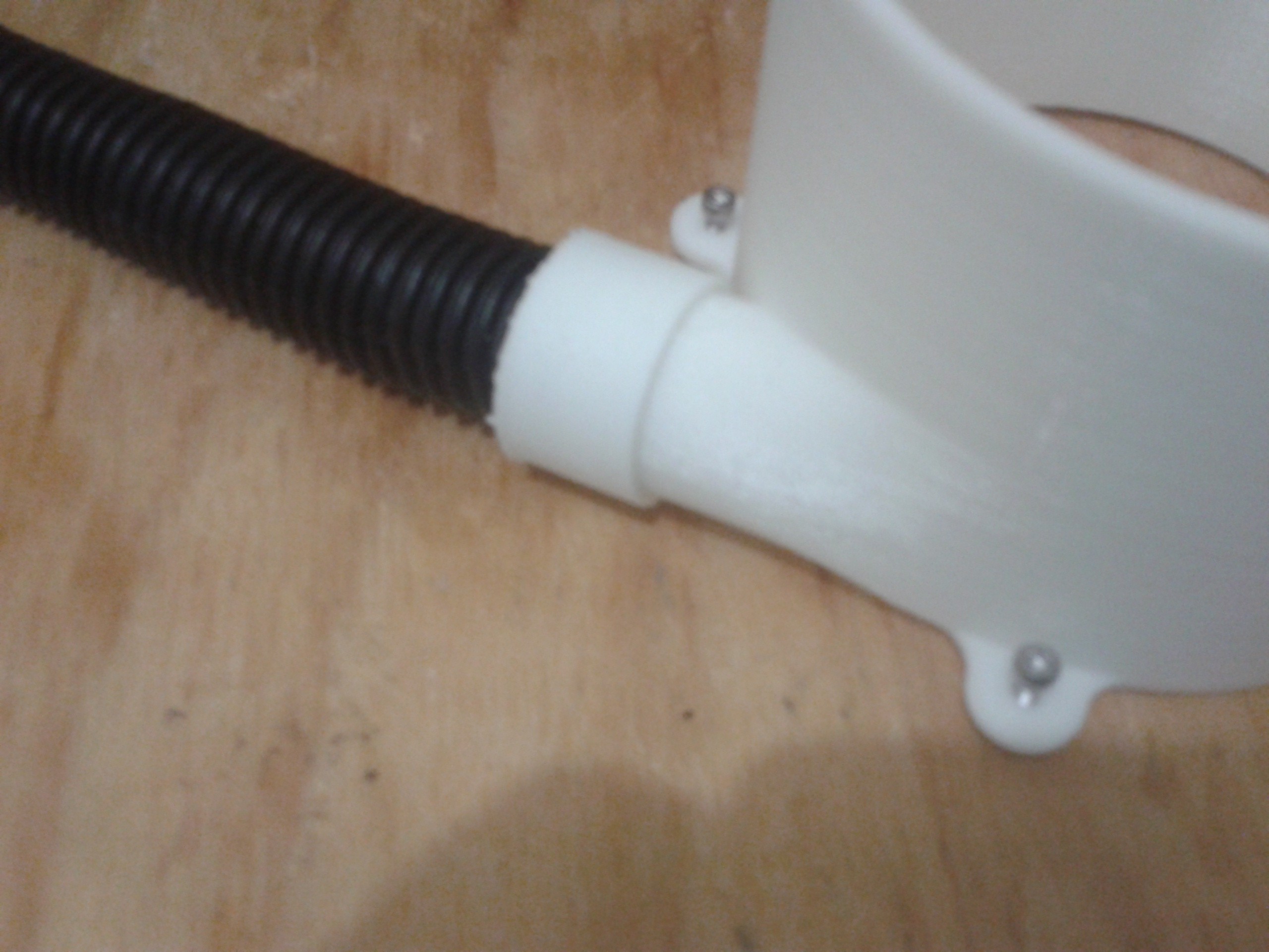
The hose needs to sit there then turn and exit just where that dark circle is drawn because the filter that i was always planning to keep took the remaining volume. However, it turned out that the hose would fit inside the inlet perfectly creating a stable seat.
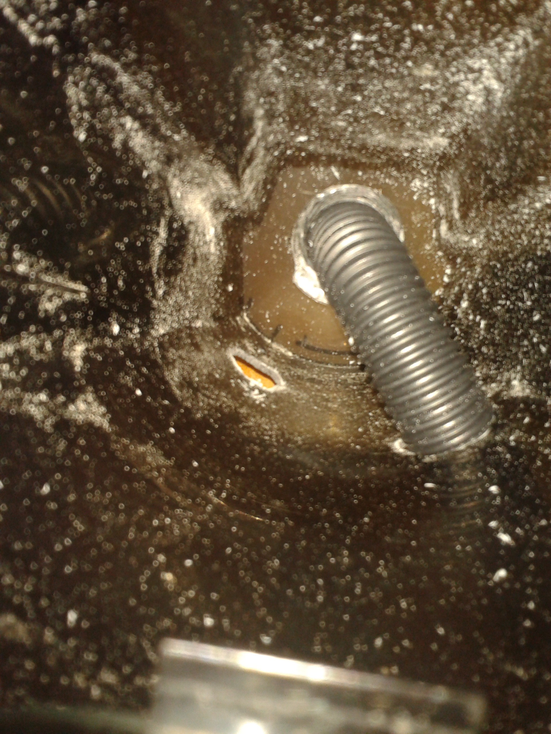
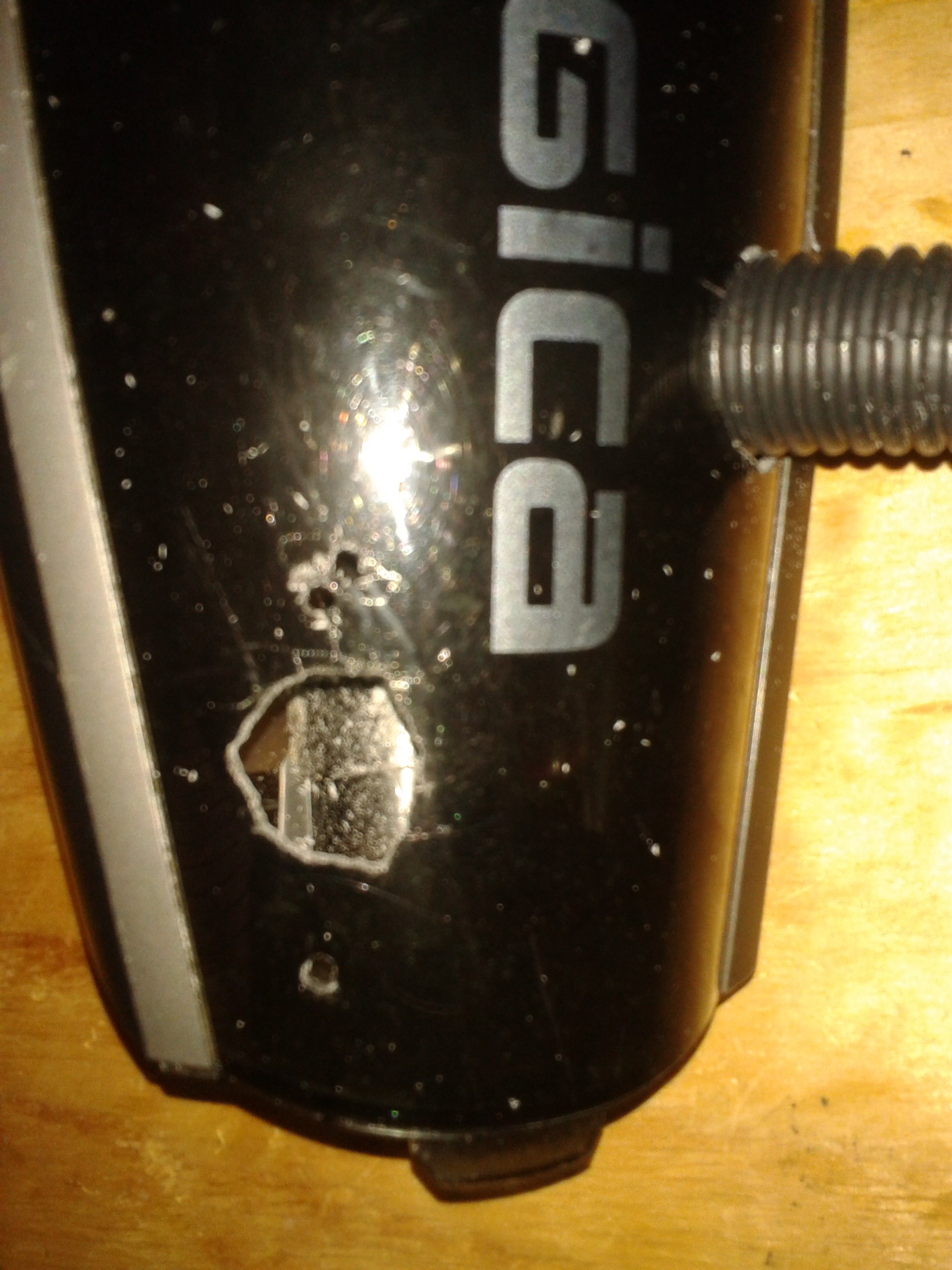
No going back from here the holes where drilled and filled, and the hose inserted.
Going back a few steps because I printed the extractor first, but these images illustrated some early design decisions as to how the space inside the chamber was a major influence. For example on of the original idea was to have the extractor contained within the chamber. The tightness of space and lack of ability to model parts exactly to the shape and dimensions of the chamber ruled this out.
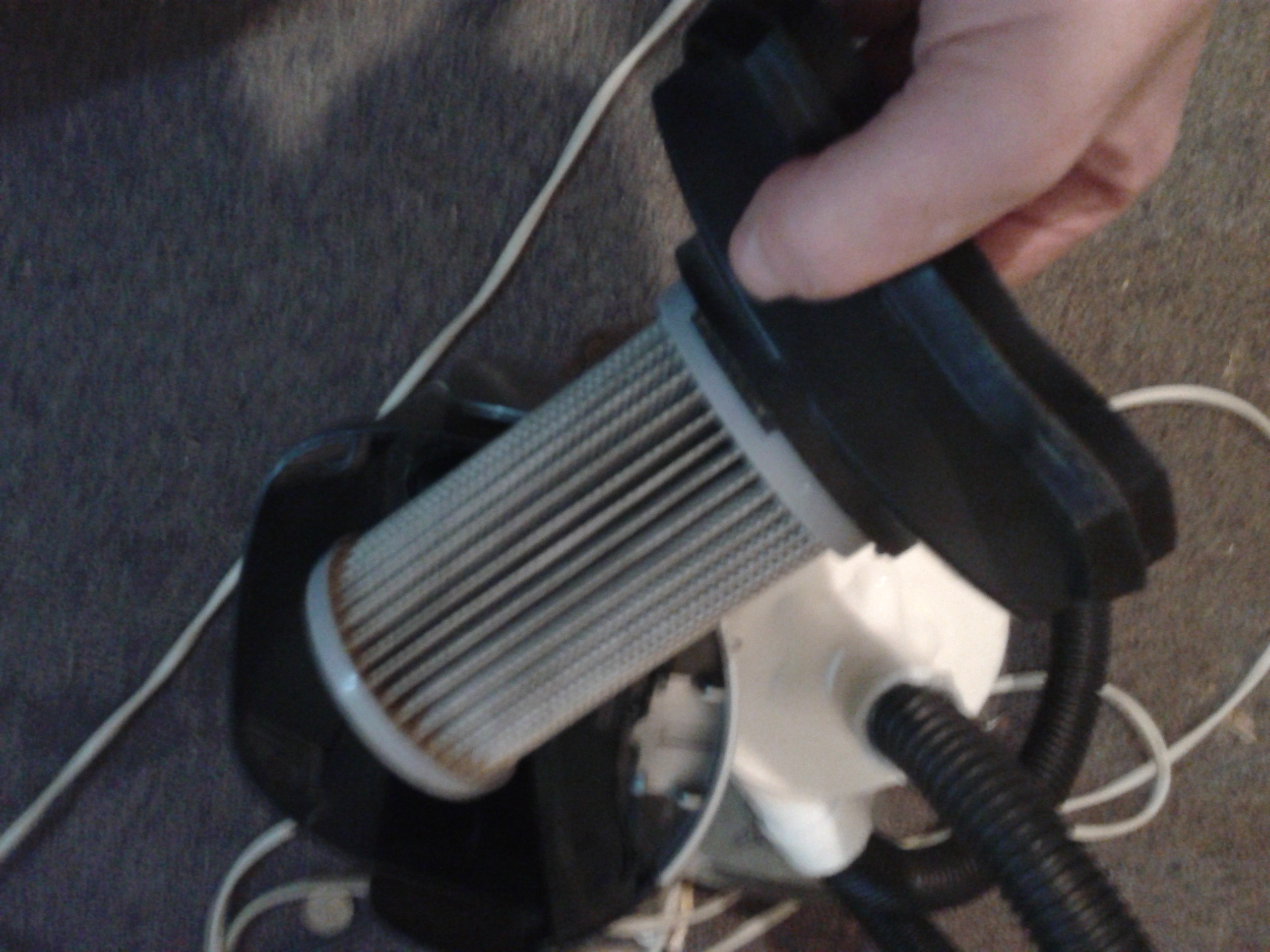
The filter and the chamber that it came from.
Design and CAD
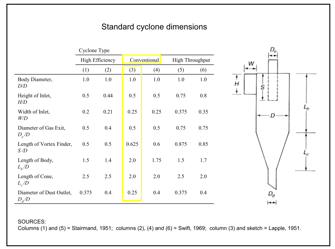
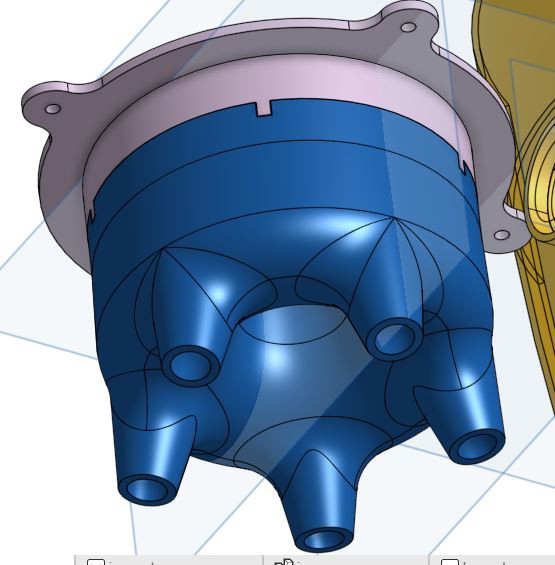
Knowing that the dust extractor is a common and relative old technology the design started from gaining knowledge of how this technology actually worked. Standard dimensions were easy to find and simulations consolidated some thinking about the lower portion of the cyclone.
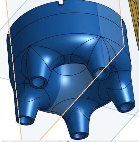
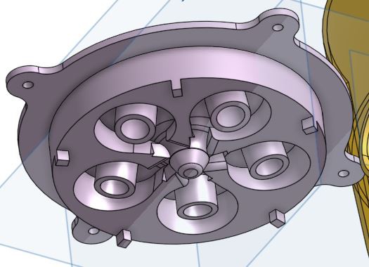
The principles set the cyclone throwing the dust to the sides and it then falls below the cyclone to the chambers floor. But, having a single cyclone would require a larger chamber and from principles it would not have a high velocity air speed. So splitting the flow into originally 4 then 5 cyclones would substantially increase the angular velocity.
Printing the flow generator also provided design constraints but also opportunities with an organic structure separating the incoming air and the high velocity cyclones. From here however it is not clear if this provides a solution but this is what I printed. So fingers crossed.
bottom half
top half
and together
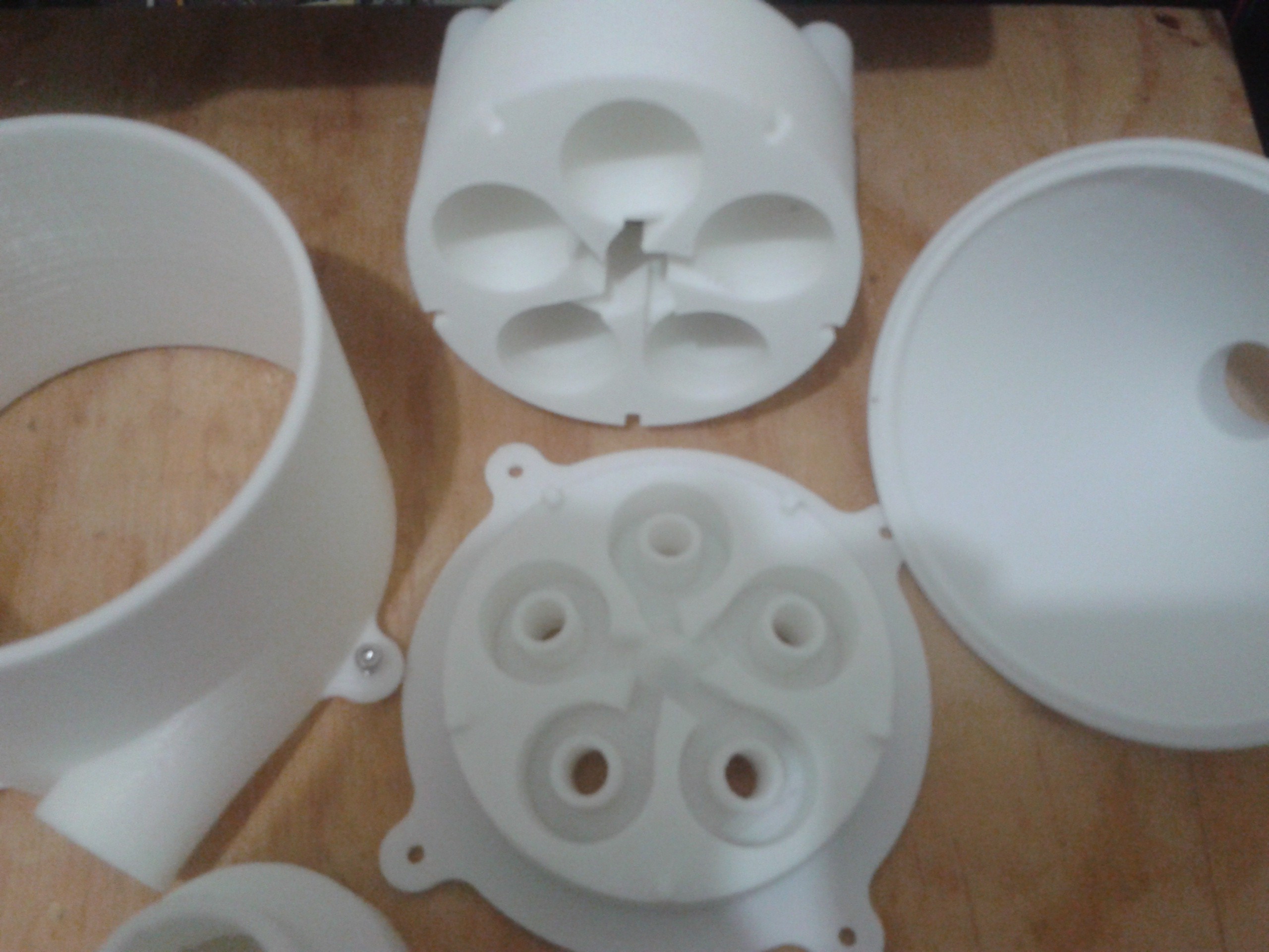
All the parts printed.
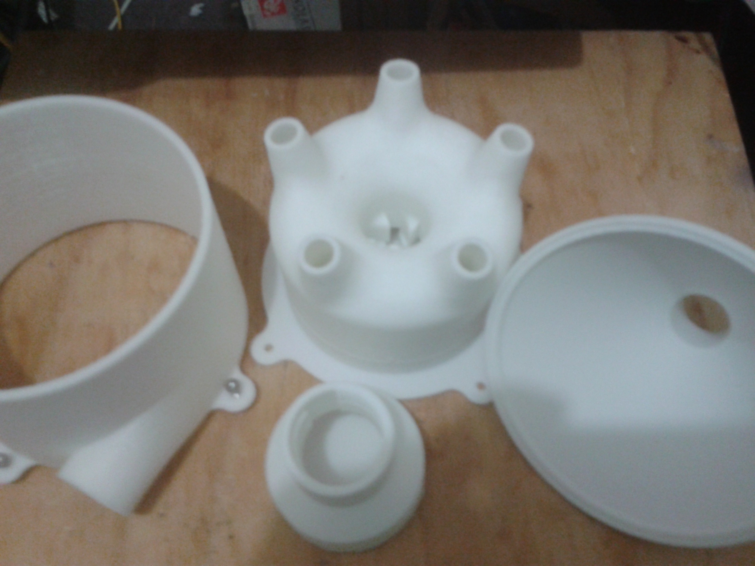
The upper and lower cyclone generator solvent welded together.
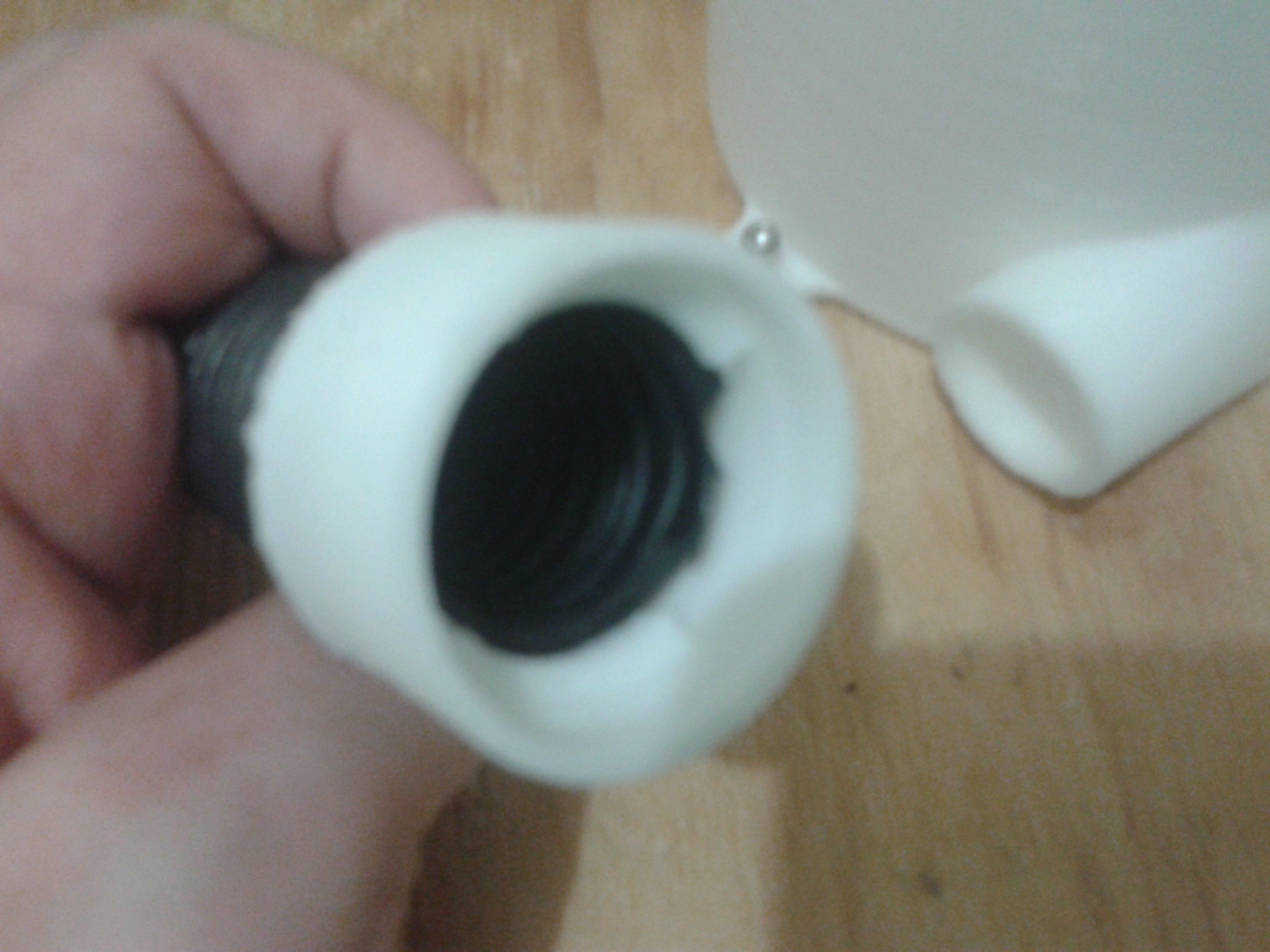
A threaded attachment was printed separately and stuck to the chambers inlet with the help of silicone.
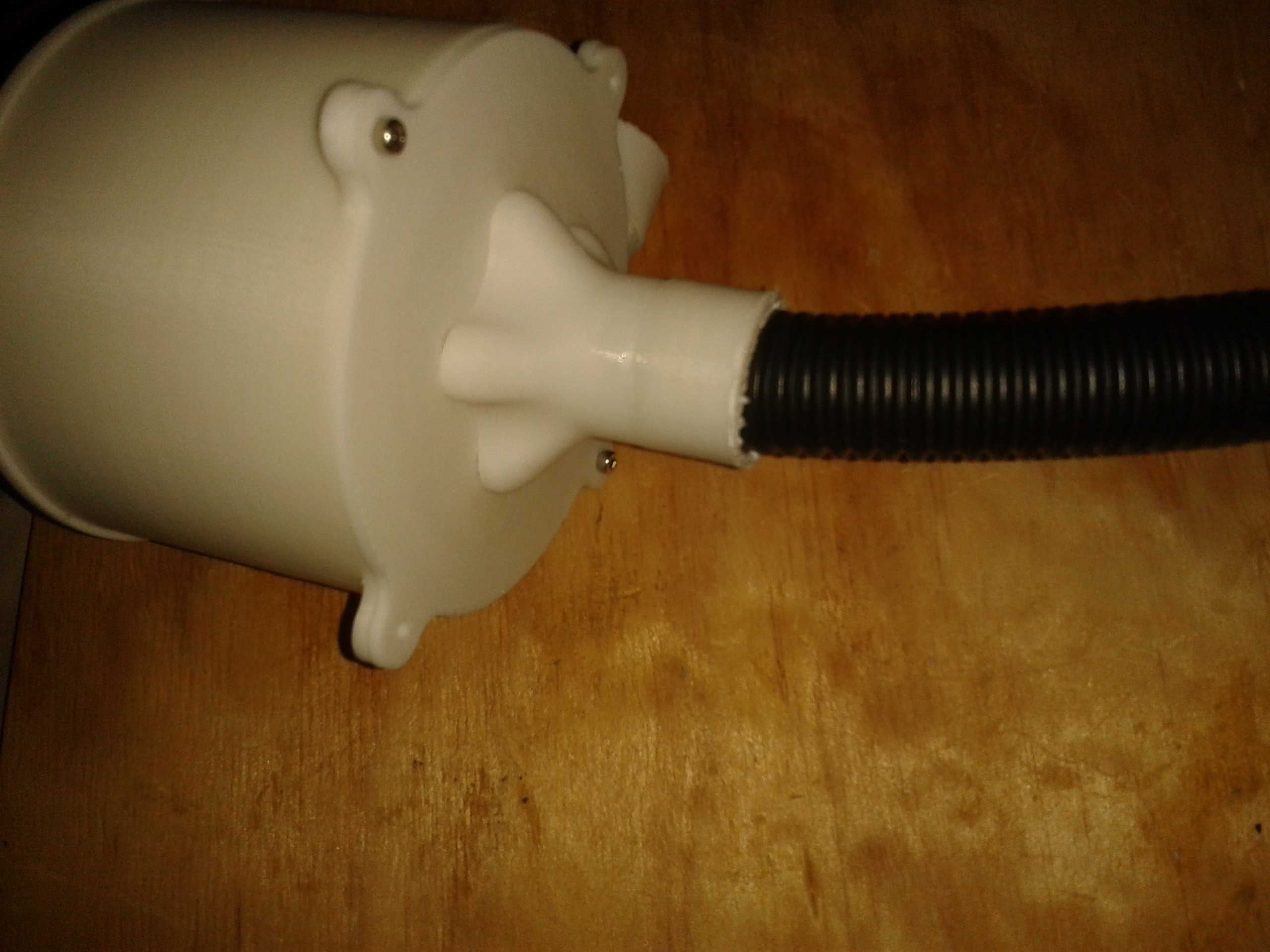
similarly the outlet
Inlet to the vacuums chamber.
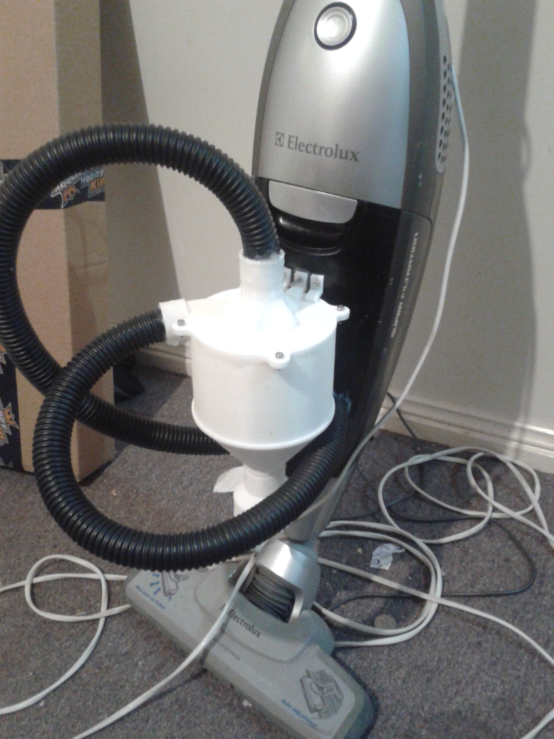
And the final result with brackets printed, solvent welded, drilled and screwed.
It does work.......
Discussions
Become a Hackaday.io Member
Create an account to leave a comment. Already have an account? Log In.