 kwan3217
Way back in the late 80s, I remember seeing a TV show (I think it was Amazing Stories) which featured an interesting clock. It was round, black, about the same size as a normal wall clock, and all done up in LEDs. The LEDs appeared to be what I now recognize as pretty normal 5mm LEDs, in a ring around the edge of the clock, facing forward. It didn’t have any numbers, but from the motion of the lights, I could tell that it had an hour hand, a minute hand, a second hand, and one hand that went all the way around in one second.
Many years later, when I got into modern hobby embedded electronics, I remembered that clock and wanted to have it. Thus was born Project Precision. I also learned about the unit of time called the "third". See, once upon a time, sundials and mechanical clocks were so inaccurate that they just showed hours. Later, as technology marched on, they divided the hour up into tiny minute parts, called minutes. When clocks got even better, they did this a second time and got the second minute, or as we now call it, the second. Yes, this is really why the primary unit of time has a secondary name. Smaller divisions were also done, each one being 1/60 of the previous. So, we have third minutes (1/60 second, about 17ms), fourth minutes (1/3600 of a second, about 278 microseconds), fifth minutes (about 4 microseconds) and so on. My clock displays hours, minutes, seconds, and thirds. Smaller than that is measurable with a computer but not visible to the naked eye.
The clock has a red ring of LEDs closest to the center which represents hours, a yellow ring representing minutes, a green ring representing seconds, and a blue ring representing thirds. I originally was concerned that the third hand going around that quickly would be annoying, but some computer animations suggested that it would be OK. Just in case, I always had in mind the ability to disable the third hand, and that ability remains -- a small change in the code would disable the third hand.
I went through a couple of iterations. The first design only used 7400 series logic, and kept time by watching the zero crossings on the 60Hz AC mains frequency. Athird in this case would simply then be one cycle of AC. This design worried me, as I was taught proper respect for high-voltage in electronics class, and anything higher than about 12V is high for me.
The clock needed to be super-accurate in order to justify displaying the third hand. I originally considered adding a WWVB receiver, but by the time I actually got to implementing the project, GPS had progressed to the point where that was the solution that made sense.
Then one day I found out about Charlieplexing. This is a way to activate an enormous number of lights using a relatively small number of control signals - on the order of O(n^2). Charlieplexing has been well-covered in other places, so I will only discuss here the practical consequences I have fallen across in my experiences.
A clock with 4 hands, each with 60 lights, requires a total of 240 lights. The exact number of lights which can be controlled by a Charlieplex with n lines is n^2-n. With n=16, we have the ability to control… exactly 240 lights. The number of available pins on an ATmega328 is… exactly 16 pins. The ATmega328 seems to have been perfectly designed for this project.
Is it practical?
The first thing to do was to check if I could really do this. I wanted a wall clock with all of its hands done with LEDs, preferably each in its own color.The parts necessary are:
- A round circuit board
- A whole mess of LEDs
- A GPS receiver module
- A microcontroller with enough pins and current drive to handle the job
It rapidly became apparent that I didn’t want to do a full 9 inch circuit board. I get boards through Laen (now oshpark.com) for $5.00 per square inch of bounding box. I figured I could afford to do a 3-inch circular board, which would cost $45 and give me three copies. A three-inch clock is too small to read across the room, so I decided to use light pipes. I designed a set of laser-cut light pipes that I could afford to get from Ponoko.
My original design with the conventional multiplexer was to have a stack of boards. One board would support the microcontroller and the 7400-series chips necessary to drive one hand, while the other three boards would just have the multiplexer. I wasn’t looking forward to spending $90 for boards for a single clock, but I couldn’t figure out any way to get enough lights onto the edge of a single board.
I had experience with doing surface-mount soldering from other projects that I had done, so I was confident with using surface-mount parts. This allowed me to use a much smaller board.
Starting Out
The first steps, as usual, are laying out the schematic. I knew I was going to use an ATmega328, so I copied the design from the Arduino Nano from Gravitech. This board design was released under an open-source BY-SA license. The Nano is a single-board computer about 1.7 inches long and 0.7 inches wide -- pretty small! It has 15 pins on each of the long edges, and 6 pins for programming. I downloaded the design from Gravitech and loaded it up in Eagle. One of the nice things about the Nano is that the Arduino IDE is already set up to handle it. If I kept my design close enough to the original, I would get this Arduino compatibility for free. Therefore I used the FT232 USB-to-UART interface chip, the same one that the Nano (and many other Arduino projects) use.
The ATmega328 has a total of 32 pins. Six of them are reserved for power and ground, and cannot be re-purposed. One is used for analog reference, and also cannot be re-purposed. Two of them are used for an oscillator, but can be repurposed if the internal oscillator is used. I chose to use an external quartz crystal, so that it would be possible for the clock to run accurately if there was no GPS. One of the pins is the reset pin, and while it can be repurposed, by doing so you lose the reset switch, which I wasn’t willing to give up. That makes a total of 10 pins on the left side of the chip, and therefore 22 on the right.
The controller can run within a wide range of voltages and at up to 16MHz, but it is not within specifications to run the part at more than 8MHz at 3.3V, so I chose to keep the 5V power and replace the resonator on the Nano with a high-precision 16MHz quartz crystal, and its associated capacitors.
Since this design uses the Arduino IDE, it makes sense to label all the other pins as they are on the Nano, meaning that they are digital pins 0-13 (14 in total) and Analog 0-7 (8 in total). This is the case even though most of the pins are repurposed as Pxx signals to drive the Charlieplex.
The clock uses a GPS module which needs its own power and ground, along with a two-line serial UART and a dedicated line for the pulse-per-second (PPS) signal. The latter is what would make the clock accurate enough to justify the precision label and the third hand. Therefore I needed three pins for GPS, leaving 19 pins.
Since the ATmega328 only has one hardware serial port, and since I didn’t believe that the SoftwareSerial port was good enough for this purpose, I had to figure out a way to multiplex this port. There are three things that want to talk (ATmega328, GPS, and FT232), and each wants to listen. Therefore from the point of view of each device, there are two other things that might want to talk to it. To fully switch things, therefore, we need 3x 2-to-1 multiplexers. Each one had an RX line for one of the devices on its sole output, and the TX lines for the other two devices on its inputs. Each one is controlled independently, so that any device can listen to any of the other two devices, even at the same time. All of the multiplexers had pullups on their control signals, so that the ATmega328 was talking and listening to the FT232 when it resets, making it programmable from the Arduino IDE. These three multiplexer control lines use 3 pins, leaving exactly the 16 pins that I need to control the Charlieplex. It was a sign to me from above that I needed to do this project using this hardware.
I followed my custom of having a three-digit component number for each component. The first digit indicates the general section of the board, such as the controller (section 4xx), USB interface (section 5xx), random glue logic (section 6xx), etc. From my first board design, it has become customary for me to label the controller as section 4xx. All other section numbers are arbitrary. In this project, the bridge between the front and back boards is section 0xx.
In a section, ICs and other “main” parts are numbered from x01, so the ATMega32 is U401, the FT232 is U501, etc. Passive and other smaller components are numbered according to the pin they serve on the larger components. So, a bypass capacitor on pin 18 of the ATMega32 is C418. This helped me out immensely with the component layout. Of course there are compromises in this scheme, such as pull-up resistor pack R606. It is called R606 because three of the resistors serve pin 6 on the multiplexers in section 6, but the fourth one is the pull-up on the reset pin of the processor.
Most of my components have the normal letter abbreviations. All connectors are J, all diodes of any kind including LEDS are D, crystals are Y, and switches are S.
Even though I am a programmer, I follow the general custom of starting at part number 1 in a section, so the man IC is U401, not U400. I do break this convention with the LEDs. Since they are naturally in positions 00 through 59, I number the ones for the hour hand D000-D059, the minute hand D100-D159, etc.

Figure 1 - Version 1.0 schematic (Controller)
Charlieplex layout
At this point, I had one of my greatest flashes of inspiration -- I could use two copies of the identical board as my front and back boards. A Charlieplex naturally controls lights in pairs -- when one signal is high and the other is low, one diode can be lit. When the polarity on these two signals is switched, another diode connected between the same signals in the opposite direction can be lit. What we will do is design the front board so that it only has the 120 lights in the forward direction. The boards have a pass-through connector between them, so that all the Charlieplex signals can get from front to back. We will then install the remaining 120 lights on the back board, pointing in the opposite direction. The pads for the rest of the circuit are ignored and are electrical dead-ends, not hurting anything. Therefore, I only had to design half of the Charlieplex.
I gave each signal involved in the charlieplex a logical name, distinct from the ATMega32 pin number, the internal register port number, and the Arduino digital (or analog) pin number. All Charlieplex signals are labeled P01 through P16.
I did the schematic manually -- each part had a distinct pattern. In the first section, I just connected each neighboring pair of Charlieplex signals with a diode. Since there are 16 signals, this first section has 15 diodes. The next section connected each signal with the one two pins away -- P01 to P03, P02 to P04, etc. through to P14-P16, for a total of 14 lights. The next section went from each pin to the one three pins away, and had 13 lights, etc, all the way to the last section which has one light bridging the pins 15 signals apart. In this section, Pxx is the signal connecting directly to the ATmega328, while the corresponding Qxx is connected to the diodes. Each P-Q pair is connected through a current-limiting resistor. Since the current path always flows through two signals, it flows through two resistors, so each resistor is half of the calculated value for current limiting. The value chosen is a compromise, since while each color LED has the same nominal current (20mA), each color has a different turn-on voltage, so each color in theory needs a different resistor.
All 16 Qxx signals are routed through a pair of 8-pin connectors to bridge from the front board to the back board. This is represented on the schematic by the two connectors on the bottom. The back board only needs its side of the connector and its LEDs -- no resistors on that board. The schematic only indicates one diode at each location. The other diode is on the other board, and this is the design for only one board.

Figure 2 - Charlieplex grid layout
The routing between the two sections is only indicated on the schematic with signal names. I wanted to indicate the design regularity on the Charlieplex side, and isolate the unavoidable irregularity on the controller side. It would not have served anyone to show a literal maze of wiring between these two sections.
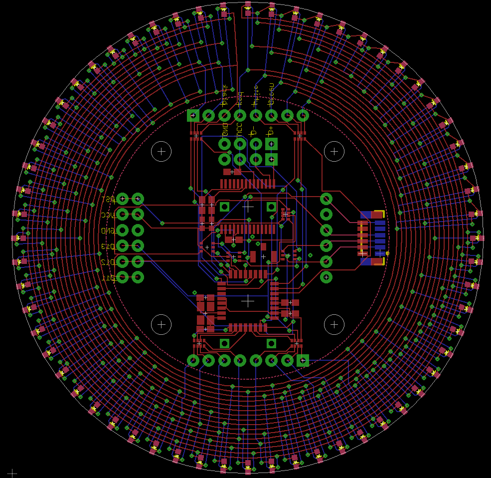
Board layout![]()

Since the board is circular, it makes sense to design it with circular symmetry. The outer edge of each board is occupied by the LEDS, the center section by the microcontroller circuit and connectors, and the section in between by the Charlieplex routing.
Just for fun, I let the auto-router have a chance. While it did develop a working board, it had no concept of symmetry or art, and just threw down wires wherever it needed to.
So, through a combination of a spreadsheet which I used to create ULP code for Eagle to place the lights and signals, and a bit of manual routing, I came up with a routing pattern which has a pleasing amount of symmetry.
On the front side of the board are a bunch of circular traces, one for each Charlieplex signal, 16 in total. These are spaced as close as possible while maintaining clearance between a via on one trace and its neighbors on either side. The rails could have been completely circular, but circuit loops are aesthetically displeasing to me. I like my little electron servants to have one and only one path. So, the circular rails are broken near the 12-o’clock position. Besides, this saves one via (on a board with hundreds).
On the back side are radial traces connecting each pad with its required signal. Because of the regular pattern of the lights, the vias created interesting spiral patterns themselves. Each position from 00-59 had two lights, one on the front, and one on the back. The lights for a particular position had no special relation to each other, so each drew from different rails. There are a maximum of 4 radial connections to each position. However, positions from 0-14 could connect to each other on the front side and share one radial rail, leaving only 3 for each position.
All other components are either on the front side of the board, or are through-hole, with the exception of the GPS socket. I wasn’t sure which board and which side of the board would be most convenient, so I allowed for all possibilities by putting pads for the socket on both sides.
Oops…
Once I ordered and received the board and parts, I soldered down the controller circuit in the middle first. Since it is a proper Arduino, I used another Arduino to jump-start this one by burning the Arduino boot-loader onto it. I then plugged in the USB cable and uploaded a sketch. Because this device, which was about to be full of lights, didn’t have any lights to begin with, I used the example Arduino sketch which prints the ASCII table. And it worked!

After that, I soldered on a single LED to the outside edge of the board. A little bit of consultation of the schematic, a small sketch, and voila, we have one light that lights. One down, 239 to go. I always soldered a few, then tested a few, using a sketch which is specifically for the purpose of manually lighting one light at a time. But...
Lights 4 and 5 on the back of the second board (where I am installing the blue lights) won't light. As it happens, neither will any of 54-59, but we'll save that part of the story for later.
When I assembled the controller circut, I remember that there was a solder bridge that I fixed between two pins, and one of those pins, A7, is involved with the lights that don't work. So, we carefully measure pin A7 and conclude that no matter how we program it, it acts like a high impedance. The natural conclusion is that it is burned out. So, run to Sparkfun, buy their last three ATmega328s, and a hot air rework station to pull the old chip. Carefully remove the old chip, taking care not to scorch the white paint on the board or blow away any of the passive components. When the chip comes off, it comes off great. Put in a new chip, verrrry carefully check continuity between each pin to make sure there are no bridges or missed joints. Fix a couple of missed joints. Guess what. The board acts exactly as it did.
So, that theory is shot. I might have burned out pins on this chip, but exactly the same pins? I think not. Now time to gather more evidence for another theory. Write up a program that listens for commands on the serial port and turns individual signals high or low, with the rest at high-Z. Signals 1 and 16 are both no good. What is going on?

The Arduino documentation says that you can use the analog input pins A0... as normal digital pins with the syntax pinMode(A0,OUTPUT); digitalWrite(A0,HI); etc. Which is in fact true, but only to a point. On an ATmega328, pins A6 and A7 are internally called ADC6 and ADC7, not PB...(ADC6) or anything like that. They are dedicated input pins. I had been planning (as in had a circut board made) to use A6 and A7 as Charlieplex lines 1 and 16. Guess which Charlieplex lines don't work... And guess which signals lights 4 and 5 (and 54-59) use...
I have no one to blame for this but myself. It was right on the Eagle schematic symbol the whole time that all the other A0... pins were secondary uses of GPIO pins, but A6 and A7 were only labeled as ADC. You can repurpose the reset and oscillator pins, but not these two analog pins. How much sense does that make?
To prove this theory, I used lots of green wires, hot air, and razor blades, to hack D11 and D12 into P1 and P16. This required giving up two multiplexers, which completely hashed my plan to use the GPS. But at least this I got to test the whole Charlieplex.
I redesigned the board to not use the two pins in question, and gave up on fully routing the serial signals. Instead, there is a single multiplexer which lets the ATmega328 listen to either the FT232 (default) or the GPS. The GPS and FT232 both listen to the ATmega328, so all GPS commands get printed, and all print statements get sent to the GPS, which ignores them because they aren’t properly formatted.
With that 1.1 spin of the board, I also switched GPS units. The new board uses the UP501 GPS unit, which runs on 3.3V. I originally was going to use a 1.1 board as the front board and re-use the populated 1.0 back board, but it turns out that the GPS connections were not compatible and it would have had a short from 5.0V to 3.3V. The UP501 has a through-hole connector. I soldered a 6-position stackable header to it, so I could use either the pins to plug it into a breadboard, or the holes to plug wires into it. I put another stackable header on the back of the back board, and rearranged the pinout of that socket to match the UP501 so it can be plugged in directly.

Figure 3 - Controller schematic v1.1
Charlieplex Library
To support both my manual testing program and the actual operation of the clock, I created a small Arduino library, PCharlie. The interface is a few small functions, which allow the code to turn on one light, to turn off the light which is currently on, and to turn off all the lights.
//PCharlie.h

#ifndef PCHARLIE_H
#define PCHARLIE_H

#if defined(ARDUINO) && ARDUINO >= 100
 #include "Arduino.h"
#else
 #include "WProgram.h"
#endif

extern bool PCharlieVerbose;

void allDark(void);
void dark(void);
void light(int);

#endif
The function light() is the only truly interesting function in the bunch. Pass it a 3-digit decimal number, where the hundreds digit is the “hand” (ring of lights) to use, from 0xx to 3xx, and the tens and units identify the position in the hand to light, from 0 to 59. Any number out of this range is safe, and results in all lights being turned off.
In accordance with the concept of “Smart Tables and Stupid Code”, most of the complexity is built into a series of tables which identifies which pins are used to control which lights.
//PCharlie.cpp
#include "PCharlie.h"

bool PCharlieVerbose=false;

static const signed char P[]=
//    1 2  3 4 5 6 7 8 9 10 11 12 13 14 15 16
 {-1,11,4,10,9,8,7,6,5,3,A5,A4,A3,A2,A1,A0,13};
static const signed char KK1[][60]=
// x0  x1  x2  x3  x4  x5  x6  x7  x8  x9
 {{ 1,  2,  3,  4,  5,  6,  7,  8,  9, 10,//00x
   11, 12, 13, 14, 15,  1,  2,  3,  4,  5,//01x
    6,  7,  8,  9, 10, 11, 12, 13, 14,  1,//02x
    2,  3,  4,  5,  6,  7,  8,  9, 10, 11,//03x
   12, 13,  1,  2,  3,  4,  5,  6,  7,  8,//04x
    9, 10, 11, 12,  1,  2,  3,  4,  5,  6}, //05x
{   7,  8,  9, 10, 11,  1,  2,  3,  4,  5,//10x
    6,  7,  8,  9, 10,  1,  2,  3,  4,  5,//11x
    6,  7,  8,  9,  1,  2,  3,  4,  5,  6,//12x
    7,  8,  1,  2,  3,  4,  5,  6,  7,  1,//13x
    2,  3,  4,  5,  6,  1,  2,  3,  4,  5,//14x
    1,  2,  3,  4,  1,  2,  3,  1,  2,  1}};//15x
static const signed char AA1[][60]=
// x0  x1  x2  x3  x4  x5  x6  x7  x8  x9
 {{ 2,  3,  4,  5,  6,  7,  8,  9, 10, 11,//00x
   12, 13, 14, 15, 16,  3,  4,  5,  6,  7,//01x
    8,  9, 10, 11, 12, 13, 14, 15, 16,  4,//02x
    5,  6,  7,  8,  9, 10, 11, 12, 13, 14,//03x
   15, 16,  5,  6,  7,  8,  9, 10, 11, 12,//04x
   13, 14, 15, 16,  6,  7,  8,  9, 10, 11}, //05x
  {12, 13, 14, 15, 16,  7,  8,  9, 10, 11,//10x
   12, 13, 14, 15, 16,  8,  9, 10, 11, 12,//11x
   13, 14, 15, 16,  9, 10, 11, 12, 13, 14,//12x
   15, 16, 10, 11, 12, 13, 14, 15, 16, 11,//13x
   12, 13, 14, 15, 16, 12, 13, 14, 15, 16,//14x
   13, 14, 15, 16, 14, 15, 16, 15, 16, 16}};//15x

signed char pinA,pinK;

void allDark() {
  pinA=-1;pinK=-1;
  for(int i=1;i<=16;i++) pinMode(P[i],INPUT);
}

void dark() {
  if(pinA==0) return;
  pinMode(pinA,INPUT);
  pinMode(pinK,INPUT);
  pinA=-1;pinK=-1;
}

void light(int x) {
  int h=x / 100;
  int m=x % 100;
  int dir=h / 2;
  int bank=h % 2;
  dark();
  int PA=AA1[bank][m];
  pinA=P[PA];
  int PK=KK1[bank][m];
  pinK=P[PK];
  pinMode(pinA,OUTPUT); digitalWrite(pinA,dir?LOW:HIGH);
  pinMode(pinK,OUTPUT); digitalWrite(pinK,dir?HIGH:LOW);
  if(PCharlieVerbose) {
    Serial.print("Dir ");
    Serial.print(dir,DEC);
    Serial.print(" Bank ");
    Serial.println(bank,DEC);
    Serial.print("Setting P");
    Serial.print(PA,DEC);
    Serial.print(pinA>=A0?" (A":" (D");
    Serial.print(pinA>=A0?(pinA-A0):pinA,DEC);
    Serial.print(") to ");
    Serial.println(dir?"lo":"HI");
    Serial.print("Setting P");
    Serial.print(PK,DEC);
    Serial.print(pinK>=A0?" (A":" (D");
    Serial.print(pinK>=A0?(pinK-A0):pinK,DEC);
    Serial.print(") to ");
    Serial.println(dir?"HI":"lo");
  }
}
The table P[] identifies which pin is associated with which which Pxx signal. It is in the form of an array, such that P[1] is the correct Arduino pin number for P01, P[2] for P02, etc. P[0] is not used. If you are building on this project, customize this table to match your Charlieplex signal grid.The table KK1[][] and AA1[][] identify the cathode (think kathode) and anode for each position. The first index is 0 or 1, and identifies which hand ring we are working on. The second index ranges from 0 to 59 and identifies the position in the ring. In the KK1[][] table, the entry in each cell identifies which Pxx signal is attached to the cathode (low voltage pin) of the LED in this hand and position. Likewise, AA1[][] identifies the anode (high voltage pin). So, to light a particular light in rings 0 or 1, look up the cathode Pxx in KK1[][], the anode Pxx in AA1[][], and set the cathode pin to low and the anode pin to high. Set all other pins to INPUT so that they are high-impedance, effectively disconnected. To light the corresponding LED in ring 2 or 3, reverse the polarity of the signals, IE set the KK1[][] pin high and the AA1[][] pin low. These tables were manually created, but the pattern is simple and identical to that used for wiring the grid schematic. The KK1[][] table starts at 1 and counts all the way up to 15, then goes back to 1 and counts up to 14, etc, for each column of the Charlieplex grid until we reach the last column, which only has 1. The AA1[][] starts at 2 and counts up to 16, then goes back to 3 and counts to 16, etc, until we reach the last column, which only has 16. The pattern in both cases continues right through the break between rings. If you are building on this project, customize these tables to match your LED array.
The function light() actually implements this logic. There is some logic which first turns off any light which might be on by calling the dark() function. When passed a three-digit light number, say 123, it first calculates the ring number by dividing by 100 (getting 1), and the position number by taking the remainder (getting 23). If the ring was 2 or 3, the code will look up 0 or 1, but remember to swap HIGH and LOW. It then looks for the right cathode in KK1[1][23], which is 9 (indicating P9) and the right anode in AA1[1][23] which is 16, for P16. It then looks up in table P[9] and P[16] to find that the cathode and anode are digital pins 3 and 13 respectively. Since the ring is 1, the code sets pin 3 to OUTPUT and LOW, and pin 13 to OUTPUT and HIGH. It also stores the cathode and anode pin numbers which it is using, for the dark() function.
All of the code in light() is organized so that the time between turning off one light and turning on the next is minimized, to maximize the apparent brightness of the clock. There is code for debugging purposes which prints to the serial port which pin is set to which level. This code is normally disabled, and enabled by setting the variable PCharlieVerbose to true.
The function dark() uses the stored anode and cathode numbers and sets those pins to INPUT, which turns off the light which was on.
The function allDark() uses the P table and turns all the Pxx signals to input. This is not used in normal logic because it takes eight times as long. It is only used during startup to make sure all the pins are in their proper state.
Precision testing code
This code is used to exercise the Charlieplex library and hardware. It sets up the serial port to have a prompt, at which the user types a number, followed by a comma. The software then turns on the corresponding light, so if the user types 123, then the light in ring 1, position 23 is lit. To enable more rapid testing, if the user types space, then the light number is incremented, taking care to bridge gaps between rings (such as from 059 to 100) and between the last ring and the first (between 359 and 000). This code was invaluable in debugging the Oops above. If there had been any errors in the circuit board, this program would have found them, but by that point it would have required a board respin to fix.
NMEA Parsing
NMEA parsing is done by a finite state machine. This machine is implemented with each state represented by a boolean function, and the state variable as a pointer to the function. The function pointed to by the state variable is the current state. Calling it with the next character received from the serial port will progress the state machine.
Each state function looks at what it is passed, and decides what state to go to next. It may also set variables, etc. So, for instance, the state function which is looking for a digit to go into a particular clock variable will modify the clock variable appropriately when it sees a digit and go on to the next state, or it will crash if it doesn’t see a digit.
The term crash has a technical definition for state machines. Whenever there is an input which the state was not expecting, the crash action is to go to some crash state. In the case of this machine, the crash action is to go back to watching for the beginning of the next sentence, which will start with a dollar sign ($). This crash state is therefore called expectDollar() . This state is also the start state.
This state machine is looking only for GPRMC sentences, as documented at http://aprs.gids.nl/nmea/#rmc . From this, we only care about the time stamp and the date stamp. The code is in RMC.h and RMC.cpp.
Each expectXYZ() function does pretty much what it says on the tin. If the character it expects turns up, it advances to the next state, otherwise it crashes back to expectDollar().
The expect<digit>() functions are a bit more interesting. They are all alike in that they are looking for characters between ‘0’ and ‘9’. If another character appears, the machine crashes back to expectDollar(). However, the difference between all these routines is as follows. Each expect<clockVar>X() function works on a different clock variable, which together hold the time and date to integer second precision. The expect<clockVar>0() functions look for the digit in the tens place, and sets the corresponding clock variable by subtracting the ASCII code for ‘0’ from the ASCII code for the input, leaving the value of the digit. This value is then multiplied by 10 and stuffed in the correct clock variable. The expect<clockVar>1() does the same digit value calculation, then adds the value to the correct clock value, which already has the tens value from the previous state.
Since we don’t care about the position of the clock, we skip all the fields in the middle of the sentence dealing with position. We do this by counting commas with the countCommaToDate() state. This function is unique in that it will never crash. The previous state (expectSecond0()) sets the number of commas to skip. Then whenever this state sees a comma, it decrements the counter. If it doesn’t see a comma, it stays in the same state. If it does see a comma and decrement the counter, it stays in the current state if the counter isn’t yet zero, and only advances to the next state once it simultaneously sees a comma and the counter has hit zero. The result is that the correct number of comma-separated fields of any length are skipped. If there is an error in transmission, the comma-counter doesn’t care. It just sees or doesn’t see commas, until it sees the number it cares about. If the comma-counter skipped over an error, it is very likely that the following states will not sync up, and will crash when they don’t see what they expected.
All of these functions return a boolean value, indicating whether a complete sentence has been read, and the GPS time variables are valid. The time variables are ONLY valid in between the time that one call to process() returns true and the next time process() is called, so the calling code must copy the GPS time values to someplace else immediately upon seeing that process() returned true. We will see how that happens in another module.
Having said that, almost all of these states can only return false. Only the expectYear1() state can return true. It is the state which handles the ones place of the year, which happens to be the last digit of the date and the last character of the sentence that we care about. If this state sees a digit, it finishes loading the Year variable, then checks whether all the time variables are within their expected ranges. If they are, then and only then does the state return true, because then and only then is there a complete set of clock variables ready to go. The next state is expectDollar(), whether or not this test passes.
The NMEA protocol has a checksum to help defend against bad data getting into an autopilot, which might think that it was thousands of miles off course if one digit of the position was messed up. Since we are not driving an autopilot, but a clock, the only consequence of bad data is that the clock display is wrong until the next sentence arrives. Therefore we don’t care about error checking, and don’t bother with checking for the checksum. In fact, the rest of the sentence after the last digit of the year is ignored, because the current state at that point is expectDollar() which is looking for the dollar sign at the beginning of the next sentence.
Time zone and Daylight Saving Time handling
First off, let me state for the record that Daylight Saving Time is an abomination upon the face of the earth. It is difficult to implement (just ask the airlines), painful to those who suffer from it, and has no benefit. The city folk think it helps the farmers, and the farmers know that the animals don’t care about clocks, just where the sun is in the sky. The only reason I can think of why such a system continues is bureaucratic inertia. The Congress decided that it could control Time itself, and doesn’t want to give up (what it thinks of as) its power over nature. Having said all that, DST is a fact of life, which must be dealt with by us mere mortals.
Time Zones, on the other hand, are an unalloyed good. The railroads which came up with the system were inspired. The only drawback is that while ideally, time zone boundaries should be put along political boundaries out in relatively unpopulated areas, in practice sometimes political boundaries are close to populated areas. Sometimes both of these things collide. Ask someone in Indiana what time it is. However, your author lives near Denver, a place near the middle of its time zone. We suffer under DST, but other than that, things aren’t too bad.
For a long time, the Precision code didn’t have an automatic compensation for DST, even though it had all the hardware and information necessary to do so. The code knew what the local time zone offset was from the UTC in the time messages, and this offset had to be changed and the program recompiled every time DST went into and out of effect.
Finally I broke down and put in proper code to handle this. This code will work either forever or until Congress changes the DST rules (again). The code is in DST.h and DST.cpp. This code has a function which determines what day of the week a particular day is, given the year, month, and day number in the month. The largest part is the code which figures out whether DST is in effect, given the local time date and hour, step by step. It first looks at the month. If the month is before March or after November, we are in standard time. If the month is after March and before November, we are in summer time. If the month is March, we have to figure out which day of the month is the second Sunday. We do that by figuring out what day of the week the first day of the month is, and using that to calculate the date of the second Sunday. If the date is before this, we are in standard time, and if after, we are afflicted by DST. On the date in question, if the local standard time (before DST offset) is before 2:00, standard time is in effect, and the time zone is whatever the standard time zone is. If it is after, DST is in effect, and the time zone is one less than normal. Similar logic is used in November.
The interface to this code is a function which is called whenever a valid GPS message is received, which copies the time from the GPS time variables to the local time variables. In the process, it uses local time offset, including DST if it is in effect. There is the possibility that some variables will be weird (such things as the date being April 0) but since this is a clock with no calendar display, things work out. The local time hour is always between 0 and 11, since there is no AM/PM display on the clock.
Precision Main Code
The main code handles such things as driving everything normally and handling the PPS interrupt.
As noted in the comments, the setup() function does the following things:
- Set up the serial port
- Send a message to the GPS to only create RMC and ZDA messages
- Turn off all the lights
- Set the serial multiplexer such that the ATmega328 listens to the GPS, not the USB. An external pullup on the multiplexer guarantees that the ATmega328 is listening to USB on reset. Otherwise, it would be impossible to program the controller. The controller always talks to both USB and GPS.
- Activate the internal pullup on the PPS line. Without this, the line floats if there is no GPS attached. I have seen cases where the clock will advance several minutes in an instant because the voltage on the floating line fluctuated when my hand was near it.
- Attach an interrupt handler to the PPS event.
The main loop does the following:
- Set the correct lights by calling the lights() function, to be explained elsewhere.
- Reads the serial port until there are no more characters left. For each character, activate the lights again (in case things tick during the reception of GPS data) and process the character.
The lights() function actually controls which light is on. A Charlieplex can only ever have one light on at a time. We want there to be four, or sometimes five, lights on at a time. To do this, the code switches back and forth between the lights as fast as it can. In order to do this, the code maintains an array describing which light is supposed to be on in each of five rings (the fifth ring will be explained elsewhere). Each time the lights() function is called, the code determines which ring should currently be active. It then lights the correct light in that ring.
Because of the optical design of the clock, some rings would naturally appear brighter than others. The red ring is on the front of the front board, and is directly visible, but is red. The yellow and green lights are not directly visible, and require the light pipes to be seen, but are green and yellow, and therefore more effective to human vision. The blue lights are the most hidden, behind multpile other light pipes and at a disadvantaged wavelength in human vision. As a result, we have a ring schedule with 16 slots. The schedule is in the array multiplex[]. Each time the lights() function is called, it advances a counter. This counter is taken mod 16 to use as the index of the multiplex[] array. The value of the cell is the ring to use. If a ring needs to be brighter, the ring appears in more slots in the array. The blue lights (ring 3) appear 9 times, the green lights (ring 2) appear 3 times, the yellow lights (ring 1) appear twice, and the red lights on front (ring 0) only appear once.
Despite having 242 lights, the clock is actually output-deficient. It can print things to the serial port, but most of the time nothing is listening (The clock is normally plugged into a USB power charger, which ignores data completely). The Tx/Rx lights are attached to the FTDI chip, and besides, the ATmega328 has no pins left to control any other lights. So, when I wanted to indicate PPS, I needed to think of some way to reuse the lights I had.
What I came up with then is ring 4. This ring is actually just re-using the red lights of ring 0. For the GPS module I am using, the PPS signal rises on the start of the second, then falls 100ms later, easily long enough to be visible if attached directly to a light. What we do instead is use ring 4. If the PPS is high, then ring 4 position 0 is on. Otherwise, position 60 is on (Out of range on a ring indicates that no lights should be on for that ring). One of the slots in the multiplex[] array is ring 4, and during that slot, the red ring indicates PPS. The effect is that the red light at the 12:00 position blinks with the PPS. If the red light in ring 0 is also at position 0, the effect is that the red light is noticeably brighter when the PPS is on.
So, the clock has enough information to light the lights. The positions of rings 0 through 2 are set directly from the local time variables. The position on ring 3 is set from keeping track of the number of microseconds since the last PPS signal was seen. The position on ring 4 is set from the PPS. All of this is done with the routine updateClock() which is called by lights().
Which brings us to the third hand. Modern timekeeping customs subdivide the second decimally, the same way all other SI units are divided. We use milliseconds, microseconds, nanoseconds, etc rather than thirds, fourths, etc. In fact, the Arduino library has a function called micros(), which is a free-running counter which starts at zero when the part resets, then counts up freely one unit per microsecond, until it loops as the count overflows 32 bits (which happens in 4 billion microseconds, or a little more than an hour). So what we do is keep track of the micros() value seen when the PPS interrupt fires, then the micros() value each time the lights are updated. Some logic is necessary to handle rollovers, but what we end up with is clock variable u, which has number of microseconds since the last PPS. This is then divided down to give us clock variable t, which is the number of thirds. All of this logic is handled in updateClock(), which also calls setClockLights() which sets the hour, minute, and second from the local time variables and the third from what we just calculated.
The PPS interrupt is handled by the well-named pps() function. Whenever an interrupt happens, the function sets the u variable back to zero, which will cause the third hand to go back to position 0 the next time updateClock() is called. It also resets the multiplexer counter back to 0, increments the local time seconds counter, and handles rollover in minutes and hours. This GPS unit follows a usual pattern that I have seen in many GPS units: It sends the PPS pulse, and then doesn’t send the data for the second until some time after. I imagine that the PPS is driven by some kind of phase-lock-loop which is forced into sync with the satellite time signals. The PPS goes off, the GPS does some calculation which gets the next fix (which may take hundreds of milliseconds), it disciplines the PPS PLL, and finally trickles the position data through the serial port.
As a result, the PPS needs to be able to increment the clock itself. Later in the second, the clock variables will be forced to match the GPS message, but most of the time, the value from the message will be the same as the value the clock already has, and the variables will be set equal to their current values.
If the PPS signal is missed, then a few things will happen:
- The u counter will progress past one million. At this point, the t counter will progress to 60 and beyond, and this will cause the blue light to turn off. No third hand will be visible, starting 1 second after the last PPS received.
- The clock will only increment if a GPS message is received
- Normal timing will not be restored until a PPS is received, and then a GPS message received before the next PPS.
I had originally had in mind to add code to make the clock run free if there was no GPS attached, but the GPS I have performs well enough that this case only happens for a second or so once every few minutes.
The PPS also has logic to print certain performance indicators once per minute. The multiplexer counter runs free and is not forced into range -- instead, the counter is modded in an expression which is used immediately to index the multiplexer array. As a consequence, this counter also counts how many times lights() has been called. Since pps() resets this count to 0, the value it reaches before it is reset is the number of times the lights were flickered in the last second, or in other words the flicker frequency of the lights in Hz. Since I am interested in this value, I have pps() print the value once per minute at the top of each minute. Typical values are around 4250Hz.
Optical Design
The clock boards are circles 3 inches in diameter. This is much too small to see across the room, and besides, the front board covers up the three rings in the back. We use light-pipes to bring the light out.
My original design was to use 60 pipes, one for each position. These would be laser-cut acrylic from Ponoko. If you imagine the boards laying on a table, the pipes would be stood on edge. I discarded this design when I couldn’t figure out a good way to attach these to the clock accurately and securely.
The final design uses 3 pipes, parallel to the boards. Each pipe is in the form of a 60-pointed star. The center part is a 3-inch circle with the majority of the center cut out, to allow for the components and connectors. There is also an individual hole for each LED. Each star point then was the hand for each position of the clock. The points are 1 inch long for the minute hand, giving that light-pipe a total diameter of 5 inches. The two-inch long hands of the second-hand ring have a total diameter of 7 inches, and the third-hand has three-inch long hands and a total diameter of 9 inches. The light pipes arrived transparent with paper backing on both sides. I carefully peeled the backing off of one side, then painted that side white, to get more diffuse reflection from it. I then very carefully peeled off the other backing, because the parts are exceptionally fragile.
In order to fill space between the boards and to get more light into the light pipes, additional laser-cut acrylic rings are added. These are 3-inch outer diameter and mirror coated. Each one is mostly cut out in the middle again, but with tabs to reach the screw mounting holes.
Final Assembly
I described surface-mounting the controller and LEDs earlier. I used normal 0.1” through-hole male and female terminals to connect the front and back boards. Each light pipe has 60 holes that go over the LEDs. So, final assembly consisted of lining up each light pipe with the LEDs, sandwiching in the mirrors, and putting screws through the four screw holes. It was straightforward enough, but hard to actually do in practice due to the fragility of the light pipes and my only having two hands.
Finally, I glued a ring to the outer edge of the large light-pipes. This ring is laser-cut acrylic again, but purple this time to match the board color. The ring has numbers at the 12:00, 3:00, 6:00, and 9:00 positions, and pointers at the other hours. This helps to teach people how to read the clock.
Future Work
The clock is now finished, and performs as I imagined. The only weakness is that the light pipes are fragile (I completely shattered the pipe one time when it fell off my mantel) and that they aren’t uniformly illuminated. What I mean by this is that even though the light pipes for the third hands are 3 inches long, only about half of its length is lit. One way to help that is to have the LEDs point out radially rather than forward or backward. This would require a board redesign to rotate the pads of each LED 90°.
Also, there are now RGB LEDs with the same footprint as the LEDs that I currently have. Using these, or two-color LEDs, I can imagine putting the whole clock onto a single board. Two-color LEDs would go on front and back, while RGB would handle all four colors on one side.
The Charlieplex has a couple of flaws. As the third hand goes around, some of the LEDs in the hour hand flicker. It’s not enough to make things illegible, but it does indicate SOME problem. The reason that a Charlieplex only lights one LED at a time, even when there might be a path from high to low through several LEDs in series, is that the multiple LEDs have to share the voltage. If the voltage across an LED is low enough, it won’t light and it won’t drop any current. However, what I think is going on is that I have my current limiting resistors sized for the blue LEDs with the highest voltage. When I light one of the blue LEDs, there might be enough voltage going across two red LEDs in series that each one lights a little bit. It may be possible to rearrange the Charlieplex such that:
- All LEDs that are the same color use the same signals. This would mean that I could put the appropriate resistor for each color on the right signal.
- All secondary paths with two LEDs are the same color as the primary path. This way I wouldn’t have trouble with two red LEDs lighting up because they are using the higher voltage for a blue LED.