 Rory
RoryI have made many changes to the engine controller. I started the project using an Arduino mega to control the fuel injectors. This did work quite nicely although I decided that I should also be controlling the engine timing, retarding the ignition on boost to avoid the inevitable detonation that would destroy the engine.
A friend suggested the Infineon line of micro controllers. These have much more processing power, many more hardware timers and a floating point unit for super-fast calcs.
I rebuilt the controller using an XMC4700_relax kit. The XMC4700 lite kit would have been adequate. The relax kit features an ethernet port, SD card slot and a CAN transceiver. I had dreams of a web server based dashboard for the car at one point. I will spend some time on this when the car is fully working.
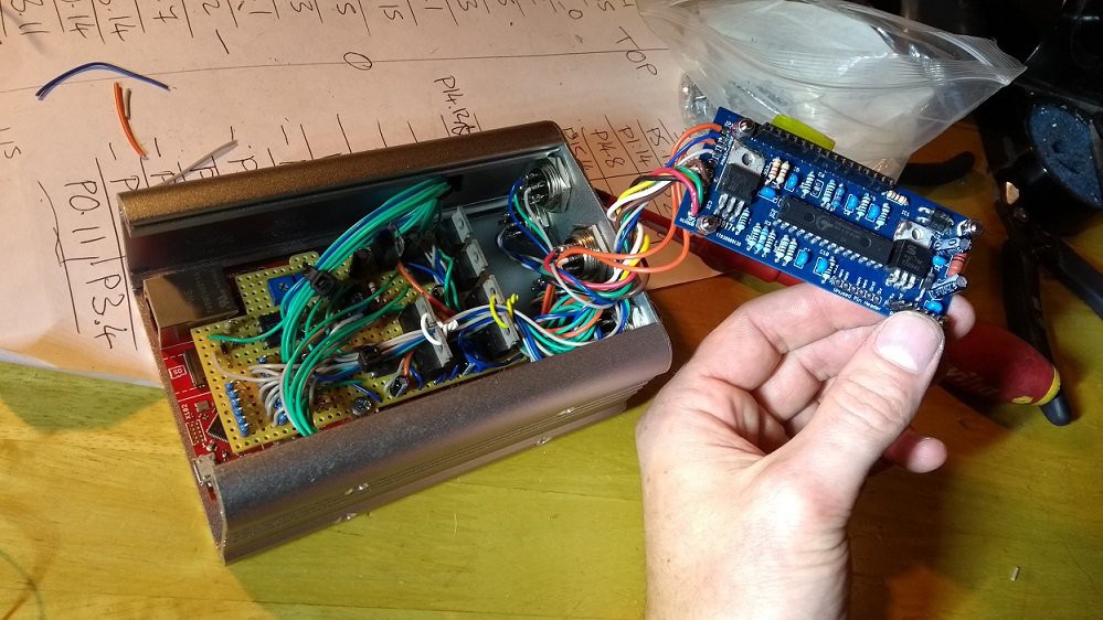
Here is the controller all wired up in its box. The blue PCB is the wide band lambda sensor controller:
The XMC4700 feeds serial data to an Arduino in the car which presents this on a LCD display. This works quite nicely. I can also connect my laptop to the USB port on the Arduino which feeds CSV data out of the virtual serial port for data logging. I spent ages looking for a program to graph and log the live data. I finally stumbled across telemetry viewer http://www.farrellf.com/projects/software/2017-02-11_Telemetry_Viewer_v0.3/ which is very good. The Arduino display also has an alarm buzzer which sounds when 100% injector duty is reached or when the fuel burn goes lean on boost.
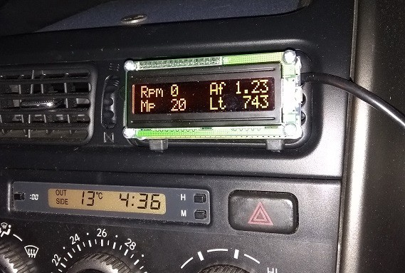
The serial data contains quite allot of information. Currently I am displaying RPM, MP = manifold pressure (gauge, mBar), Af = air fual ratio (lambda), Lt = lambda sensor temperature (°C). The lambda temperature is important because the sensor won't return an accureate reading untill the sensor is 780°C. Initially I installed the sensor too close to the output of the turbo. It wasnt getting too hot but the wide temperature fluctuations made it hard for the lambda controller to maintain the correct temperature.
I can now control the fuel injectors and add fuel where I want to based on the engine RPM and boost pressure. The pressure sensor input to the car ECU is limited at a certain voltage (to prevent it thinking the sensor has failed out to high output and cutting the fuel) this is called a ‘fuel cut defender’ in the car word and can be purchased for £140 from AEM. I made one using 1 op-amp IC. Will cad up the schematic and post at some point.
Still outstanding is control of the ignition timing. The engine uses inductive sensors monitoring a toothed wheel on the crank and cam shafts to determine its position. I am monitoring the sensors, detecting the peaks with a comparator and feeding a signal back out to the car ECU. When I want to retard the ignition, I can delay these signals.
Initially I was picking up interference causing the controller to trigger on false inputs. A RC filter sorted this out. I was getting a nice clean pulse for every high signal from the inductive pickups however the engine still would not run. A friend suggested that perhaps the car ECU is looking for the point in which the inductive sensor swings from positive to negative.
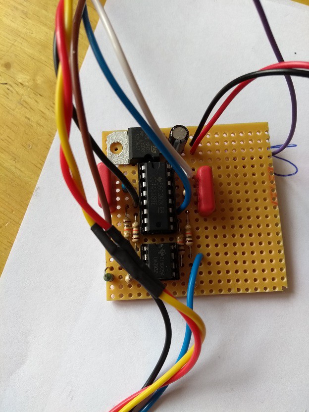
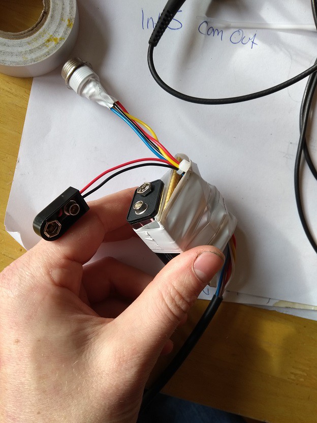
I made a circuit to add a negative pulse after the positive pulse using a cd14538. I’m temporarily using a 9V battery to get a -5V signal. This is only for testing hence the horrible bodge tape.
 |  |
This is the pulse generated. Blue is the output from the cam sensor and yellow is the signal fed to the car ECU:
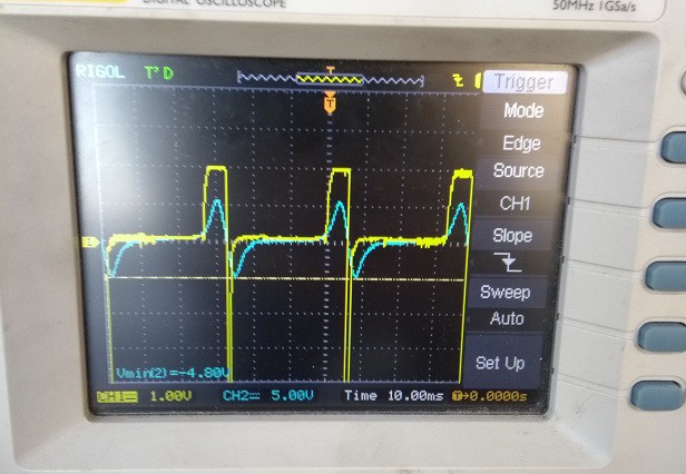
I connected this up and the engine started and ran perfectly at tick over. Increasing the revs caused the engine to cough and splutter.
Using a scope I could see that sometimes the comparator monitoring the inductive pickup would miss pulses. This happens after the missing tooth on the trigger wheel. I can increase the threshold voltage on the comparator to prevent this to a certain extent but then the small peak after the missing tooth gets missed. Also the car will not start is the threshold is more than 1V as the inductive pickup voltage is low when the engine is turning slowly on the starter. If the car ECU doesn’t detect every pulse for one crank rotation it seems to loose sync with the engine and cut fuel. 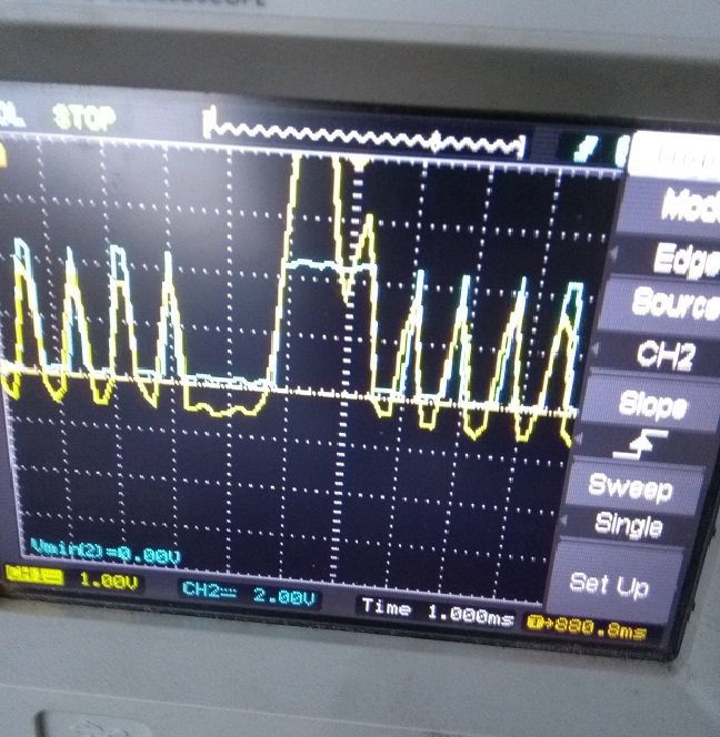
Here the yellow trace is the signal feeding a the comparator after the RC filter. The blue trace is the output from the comparator into the XMC4700.
Having throught about this the RC filter is probably to blame. It would be nice to have some more scope channels to see what the output from the cam sensor did here but I am sure it went negative. Need to reduce the C and test again.
Discussions
Become a Hackaday.io Member
Create an account to leave a comment. Already have an account? Log In.