 Neil K. Sheridan
This is the safe shutdown switch circuit, and code, for the detection and deter devices. This is so they can be turned off without risking corruption to their SD cards. This is accomplished by the switches giving a HIGH input to a GPIO pin on the Raspberry Pi when they are pressed. We take power from the VCC 3.3V pin and use the ground pin.
1.
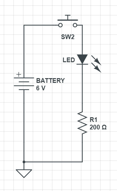
First off to build a test switch circuit on a breadboard, and power it from 6v battery pack. You'll need jump wires with male to male connectors (or just plain wires), a 200 Ohm resistor, an LED, a breadboard, a battery pack, and a momentary push button switch (normally open).
Here's the circuit:
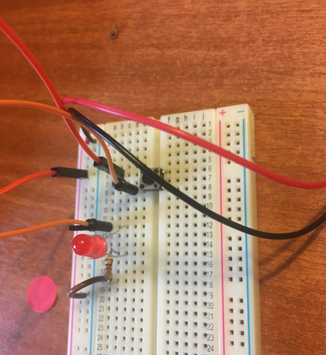
And here's a photo of it on the breadboard:
Here's a video of the circuit in action!
2.
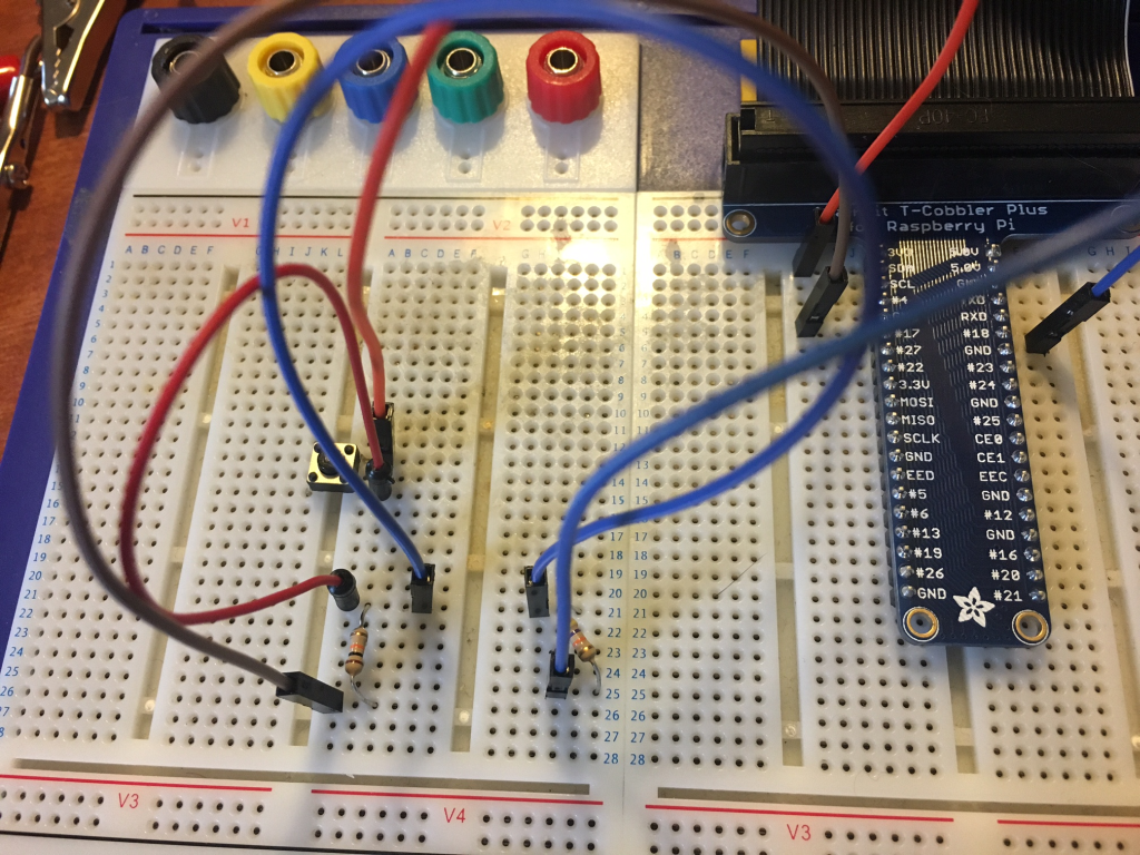
Now, let's do it with the raspberry pi (shown with the adafruit cobbler pinout prototyping device, but you can just connect it straight to the raspberry pi pins instead!).
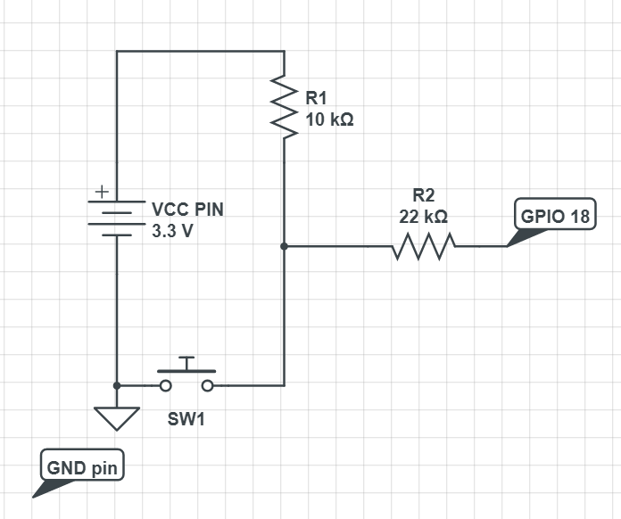
So, we used the momentary switch again, and this time we've got a 22k Ohm resistor, and a 10k Ohm resistor. You'll need a breadboard to do it on, and female to male jump wires, plus male to male (or bare wires). In the video we use an LED and a different resistor in this part of the circuit, but that's just for visual impact! Don't bother with an LED in the final circuit. You can go ahead and learn about why the resistors are required here: https://www.cl.cam.ac.uk/projects/raspberrypi/tutorials/robot/buttons_and_switches/ but certainly don't use anything under 10k Ohm.
Here's a video of the circuit in action with the LED:
3.
After building the circuit, let's see what we get from GPIO 18 when we push the button on the switch! So we need to write the following python testing code and run it:
import RPI.GPIO as GPIO
GPIO.setmode(GPIO.BOARD)
GPIO.setup(12, GPIO.IN)
try:
    while True:
             val = GPIO.input(12)
              if (val == True):
                   print("Pushed it!")
              else:
                   print("No didn't push it.. Push it now please!")
except KeyboardInterrupt:
      GPIO.cleanup()
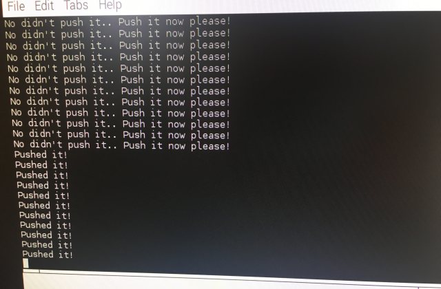
Here's what we get when we run our code, and push the button!
Here's what the circuit looks like without the LED (you can zoom in to 1024*768 image)
4.
Finally we can add the OS command to shutdown into our python code:
import RPI.GPIO as GPIO
import os
GPIO.setmode(GPIO.BOARD)
GPIO.setup(12, GPIO.IN)
try:
    while True:
             val = GPIO.input(12)
              if (val == True):
                   print("Pushed it!")
                   os.system("sudo shutdown -h now")
              else:
                   print("No didn't push it.. Push it now please!")
except KeyboardInterrupt:
      GPIO.cleanup()
Don't forget to import the os library with import os!
Here's a video of what happens when we push that button! The raspberry pi shuts down safely using the operating system command. YAY!
CONCLUSION
So now the safe shutdown switch circuit and code is all ready to be deployed on the detection and deter devices! Obviously we don't bother printing anything in the final code, or use the except, since there isn't a keyboard present! We can go ahead and deploy this circuit on a small breadboard in the detection and deter devices, or we can turn it into a PCB. For instance, the article https://hackaday.com/2015/08/21/a-tale-of-two-browser-pcb-tools/ using browser tools to design and order your PCBs!
Discussions
Become a Hackaday.io Member
Create an account to leave a comment. Already have an account? Log In.