The long-awaited update is finally here, phew, nearly 2 month's. I felt that I didn't want to make an update unless it was something that was worth mentioning.
Here's some information regarding stuff I've tried out that didn't pan out:
- Use 9 motors, 6 for each face of the cube, 3 for grabbing the female faces of the cube.
problem: Not enough space, and I know I can do better, the cube would have to be like 20x20x20 cm for this to work - Use 6 motors, 3 for grabbing the female faces of the cube, 3 for moving the grabber in an L shape
problem: Not enough space, can barely fit it all in, the cube would have to be 12x12x12 cm for this to work - Use 9 motors, like #2 above but instead of 1 motor for moving the male grabber in X or Y, it was 1 motor dedicated for X and 1 motor dedicated for Y.
problem: The cube would have to be 16x16x16 cm for that to work - Use non conductive grabbers and then, after those handles has attached to the cube, insert the male connector.
problem: It takes too much space to use dedicated grabbers and connectors
And I also tried many other wild ideas, the solution was however to use #2 above with 2x2P connector (rather than 2x3P connector as I've done so far). Smaller connector means smaller moving parts. With the 2x3P connector I could have a repeating pattern on the female side once every 20 mm, and with the 2x2P connector I could get away with 16 mm. That is a huge improvement, and that's also why the resulting cube has a weird dimension, which is 96 x 96 x 96 mm. And another reason for why this was a solution was because at #4 above I realized that I can't waste space on stuff, I need to use multi-functional tricks. So I used the connectors as grabbers by rotating the connectors 90 degrees apart, forming a lock whenever I connect the headers. Also I solved for how to use one motor to move a grabber in X and Y direction. Enough blabbing, time for some animations to illustrate the solution that I am about to 3D-print.
I like... gifs... and I will continue to upload shorts of them, because imo they are the best way to illustrate short animations. I'm trying to keep them at about 4 MB each. If people start commenting and insisting for me to use youtube/vimeo, then I'll change. But until then, gifs all the way. And that's with a hard G. I resized some gifs so they don't take so much space here on Hackaday, click for higher quality.
So this is the basic idea for how to have one motor move a grabber in X or Y direction, essentially saving one motor and it's driving components and pins on the µcontroller.
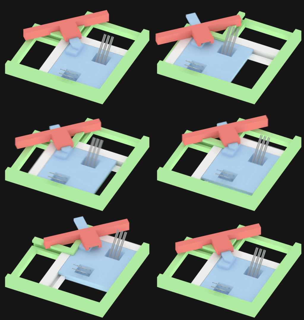 and here's another one from another angle
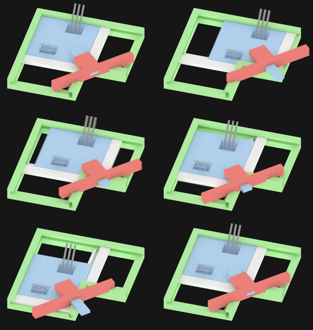
After a lot of delicate thinking, I began to think about DLIM and SLIM (Double-sided Linear Induction Motor / Single-sided Linear Induction Motor), and that's technically electric motors that has its poles unrolled from circular to flat. So I applied the same thing for gears and ended up with the solutions above. What you get is sliding sockets, and that's something that I can easily 3D-print, compared to gears, so I went a little bit overboard with the idea and used the unrolled gears for everything.
So this is how the gripping turned out:
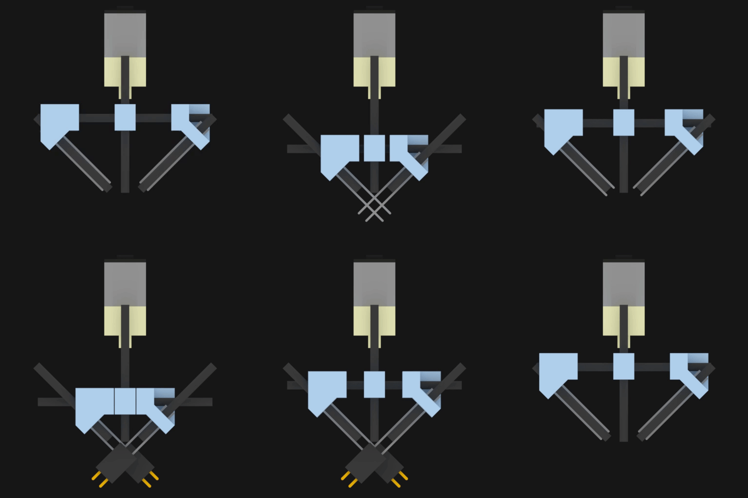 The black rectangular things are graphite rods (2mm diameter), and they are very rigid and works perfectly for sliding ABS on them. In the animation above they have the length 30 mm, it may look big, but everything is actually very small.
Here is the same thing from another perspective: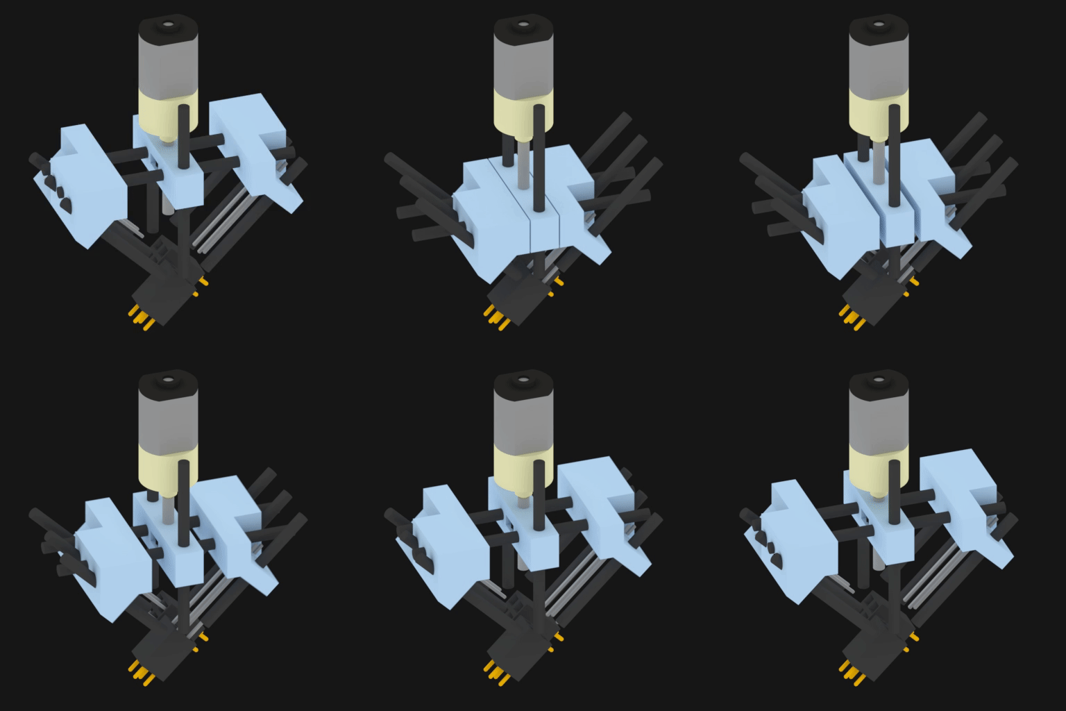
And the factor for how much extra force that is required for the motor to push vertically while the rods move at a 45 degree angle is sqrt(2) ~41% more force, compared to if the motor had been aligned with one of the tilted male headers. I made some equations on google sheets, but I doubt that anyone would find it interesting. But hey, the blue thing in the middle sits on a threaded rod connected to a planetary gear, so I'm confident that the motor will be able to handle the extra force required to push the headers out/ pull in.
Either way, this is how one side of the female side looks like:
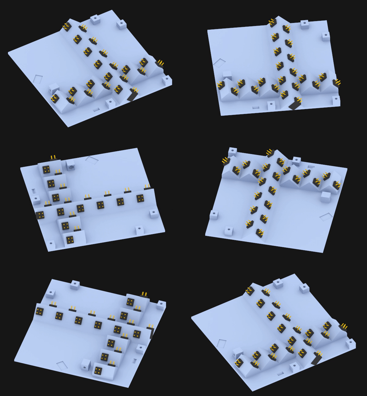 Rather than a cross I could populate a whole grid to make the cubes more flexible in their movement. But then again, just stack another cube on top and you've got your "grid". With two crosses you can form a grid.
And this is how the female sides look together, they fit rather snuggly.
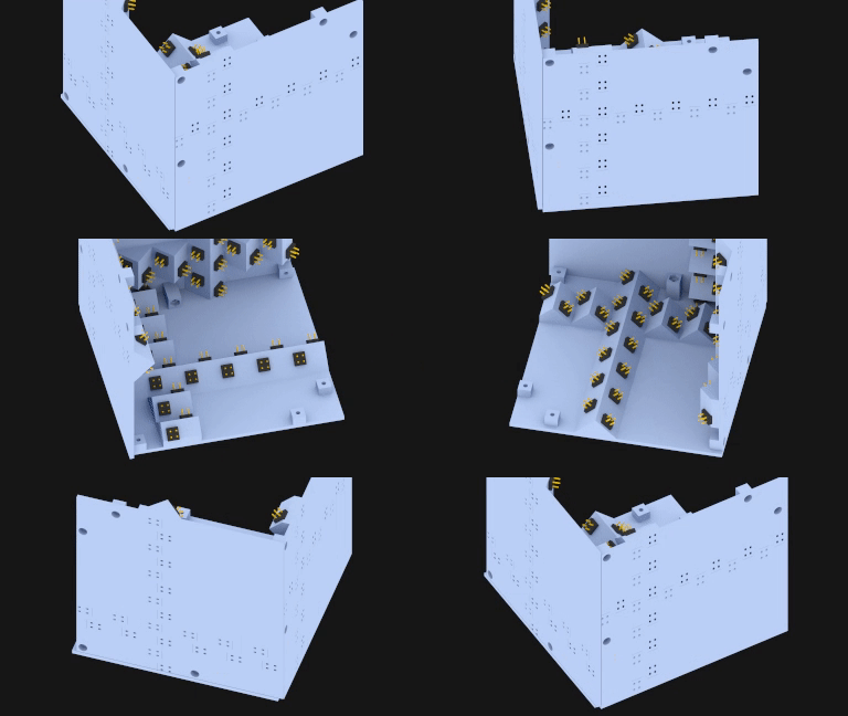 And the pins are nowhere near each other. Looks safe. If the tolerance is way too small for the male header to get into the hole which guides them to the female headers, then I'll just enlarge the guiding holes. So it looks promising.
And here's the final solution of the male header and its gripper. The one above was just an early idea.
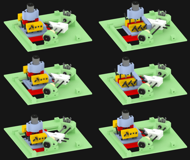
As you can see, only two motors are required per male face. I haven't 3D-printed it yet and tried it, but in "theory" it should work.
And like the female side, the male side doesn't touch each other either. It just fits. Yay.
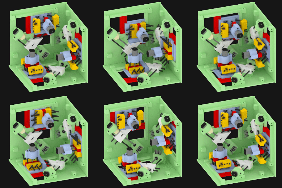
However, when the gripper platform moves towards the camera, the red guide touches the pins of a female header from the female side. So I'll have to file or do some tiny ugly hack to get the pins 2 mm to the side. But hey, as long as it works. I'll show a picture of this in a future project log where I'm assembling it.
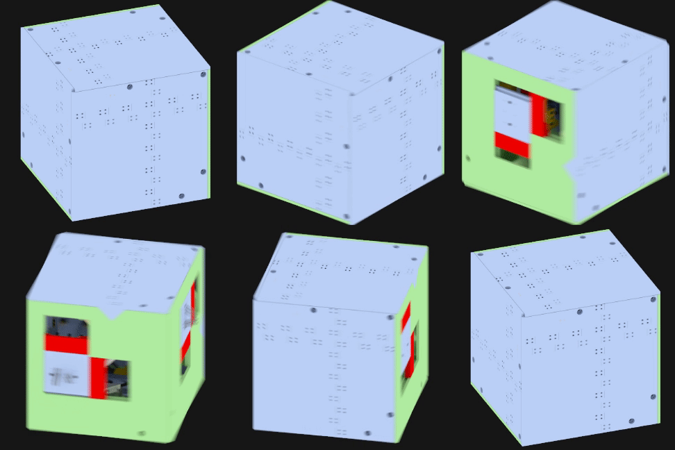 And this is how it would look like assembled, it's not perfect, I'd prefer having a cube that has total flat faces, rather than tons of holes for the female headers and 6 large holes for the gripper to move through. It's not ideal at all, and there might fall in some dust or dirt or whatever is on the floor. Oh well, that's something I'll have to think about for cube D or cube E or cube Z. Heh.
And to prove that it's theoretically possible to move it around, here's the last gif that shows that.
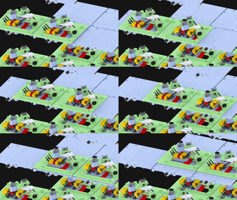
It's technically two feet that walks across the female sides. So in order for a cube to even move it has to be a minimum of two together. But that shouldn't be a problem since they are the building blocks of the system, and they are always connected. But it does however constrain the movement. In the gif just above, it's assumed that the two cubes are connected together, so when one is not connected to the one below, it receives VDD and GND from it's neighbor. Also that's where it's communication comes from. And FYI, I said I changed the header size from 3x2P to 2x2P, and as you can see there's two headers inserted at 90 degree angle => a total of 2x2x2 pins are connected => 8 pins. 2 are used for VDD and GND, 4 for data out, data in, clk out, clk in. the last 2 pins will be unconnected, reserved for future stuff.
Either way, next project log, will be very soon and consist of some 3D-prints and verification of the moving parts. After that it's time for soldering, programming, and hopefully it'll be something I won't be ashamed of for showing here on Hackaday. Which would've been the case for cube A.
I'll also upload the .blend file later, for whoever that wants to mess around.
Feedback is gladly appreciated.
Discussions
Become a Hackaday.io Member
Create an account to leave a comment. Already have an account? Log In.