The basic principle
When someone is somewhere and try to figure out where he is, he start to look around and looks for some reference points. The LRLS does exactly the same: A Laser turns around and sees where a mirror (reference point) reflects his light. When he gets a reflection he has a reference. To determine the position ether a 2nd reference is required (triangulation) or the distance to the reference point need to be measured. Both are possible with the LRLS in theory.
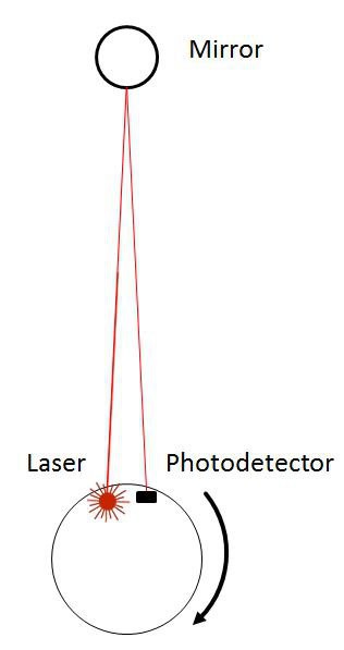
When pointing with a laser pointer to a mirror, there is only one point in the room where the light comes exactly back to the transmitter. This can be avoided by using a mirror in the form of cylinder. But still with a cylindrical mirror the light comes only on one height level and only with an exact horizontal back to the transmitter. The utilisation of a line laser avoid this and provide a certain tolerance in height as a wildly immunity against tilt angles
Visibility
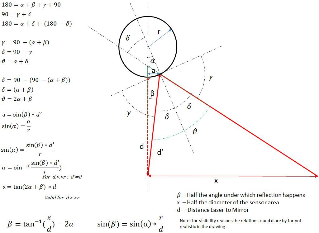
A simple test arrangement with a cylinder mirror and a line laser confirm the reflection, if the laser is strong enough and more or less on the height of the mirror. The critical point of the system is the angle (2*β) under which light comes back to the receiver. The geometry (see picture) gives only a very narrow angle under which light comes back. This angle (2*β) depends on the distance (d) between laser and mirror, a bit on the diameter of the mirror (r) and the diameter of the sensor (2*x) (see formulas on the picture). With a distance of 5m this angle is only about 0.0001 degrees. As the laser is turning around its axis, it will always hit the angle under which it reflects the light to the sensor, but it will also result in a very short pulse. This requires a very fast reaction of the microprocessor calculating the position and a high bandwidth of the electronics.
In theory the distance between the laser and the mirror can be determined with the width of the light impulse. In reality this will not work due a lot of tolerances (e.g. laser line width) and as the relation of pulse length and distance is a hyperbolic function which can’t be expressed in a y=f(x) format (or at least I wasn’t able to find a solution)
Limitations
The very narrow angle (2*β) leads to a very short impulse which gets shorter as bigger the distance between laser and mirror becomes. This requires either a very fast electronics or a low laser angular velocity. With the speed of 1 U/min the impulse length for an object in 5 meter distance is about 10µs (100kHz) which might be ok for “standard” electronics but means also that the object is sampled only once a minute. A higher sampling rate limits the distance or has a higher demand to the electronics. But anyway this is only the theory. In reality is the Laser beam by far larger than 2*β which leads to a longer Impulse anyway. The usage of two additional photo detectors would allow changing the direction whenever the laser beam passed the photo sensor. By doing this a higher sampling rate could be achieved even with a low angular velocity
The main limitation for the distance might be the amount of reflected light for large distances. A laser range finder makes with a similar principle about 40m. The LRLS has instead a line lases which provides less energy on a single spot which reduces the reach of course. But due the large angle of radiation of such a laser stronger laser can be used as the danger for the eyes is much less. In addition a mirror offers a much better reflection than a range finder does meets when pointing to any object. However the amplifier circuit requires a high pass characteristic in the range of about 400Hz (0.2m) to 100kHz (5m) this allows to eliminate any ambient light effect and make it really sensitive on received laser light.
In any case does the LRLS have very high angle accuracy even for very short distances as 10cm, 2*β is around 0.1 deg. so with all side effects a minimal resolution of 1 deg. can be expected which get much higher with increasing distance.
Realization
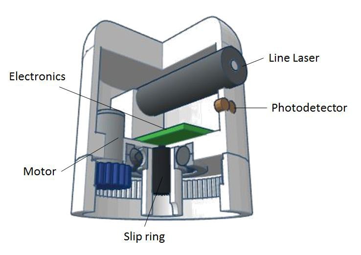
All the electronic components as LDR (or PIN-Diode), Laser, controller, etc. should be available for few dollars and easy to get. The photo sensor signal should be amplified analog with a trans impedance amplifier (TIA) with a high pass characteristics and the signal probably evaluated with a standard Schmitt trigger. The rest can be done with and Arduino or similar. For the motor a DC motor and not a stepper should be used in order to achieve a continuous rotation. The laser can be mounted on the robot or be used stationary (but then 2 are required).
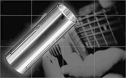
Finally the question, where to source a cylindrical mirror? The guitar players may know the “bottleneck” technique. Therefore you put a cylinder around your finger. Some of these cylinders are shiny with a chrome surface. For less than 5 dollars they can be ordered in the internet.
Context
I didn’t saw such a position system documented elsewhere yet and guess there are no patents, so I assume it’s all open source. The construction is under Attribution ShareAlike 3.0 in Tinkercad. The only protected issue found was the abbreviation RLS (Robot Localization Service). That’s why I called it LRLS.
The project might not change the world at all as there is a lot of industrial development for indoor positioning systems (IPS) and physical asset tracking. But for makers those technologies will not be available for low cost within the next few years. So the LRLS may change and enrich maker’s world and populate this world with some more robots.