Marcel van Kervinck
-
Self-awareness
06/07/2017 at 07:38 • 0 comments![]()
-
... and a blinking LED
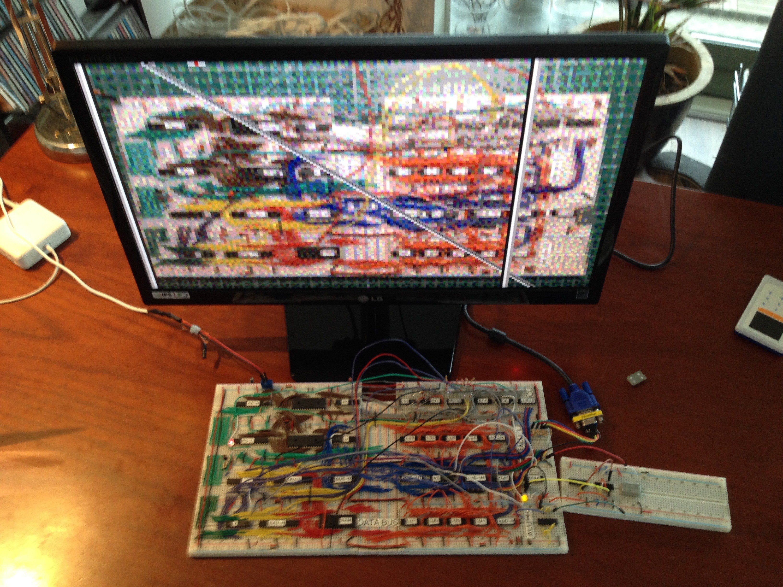
06/13/2017 at 22:44 • 2 commentsToday I realised that no homebrew CPU project can claim completeness without a blinking light. Lacking free output pins (all 8 are used for video), I hooked up an LED to the unused address pin 15, and use that as alternative.
I'm getting into some serious problems with breadboard fatigue in the EEPROM area. One of the ROM's just keeps popping out. The next phase is therefore to document the circuit in KiCad and convert it into a PCB.
[ Spoiler: the display is an older selfie, as witnessed by the incomplete wiring and background. The on-screen LED is just a 3x2 pixel area turning red at the same time as the breadboard LED. The scrolling is smooth in real life, but due to mismatch with my phone, it may appear jumpy. ]
-
Wire wrap sockets meet solderless breadboard
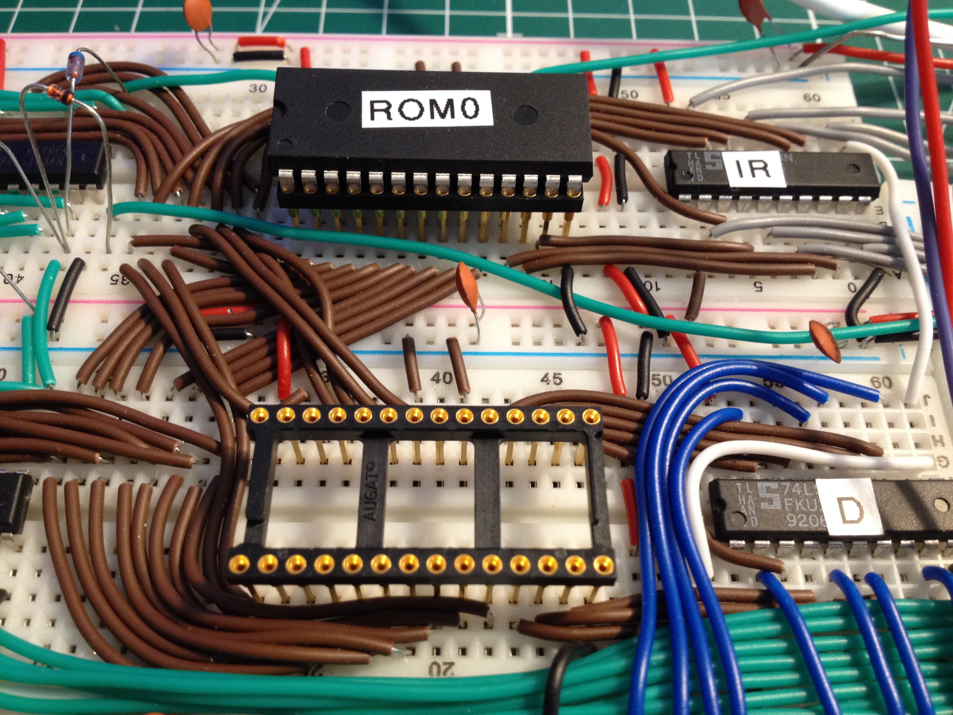
07/02/2017 at 10:28 • 0 commentsAs the programming is done externally, the breadboard suffers from the continuous removal and insertion of EEPROM's, to the point where they barely stay in place anymore. Following a comment in the Hackaday feature, this looks like a promising solution:
These are IC sockets intended for wire wrapping. I just use them for a better mechanical interface to the breadboard.![]()
-
Audio output
08/06/2017 at 16:16 • 0 commentsI've been busy adding audio output while trying to keep the component count down. First I figured out a way to insert a second output register into the circuit. It's a 74'273 that takes its input data from the accumulator and the clock from the video hsync. Good enough for 31 kHz software-generated samples and with a bit of luck I can squeeze out 4 voices. I will split this extended output register into 4 bits for audio and 4 bits for blinkenlights.
![]()
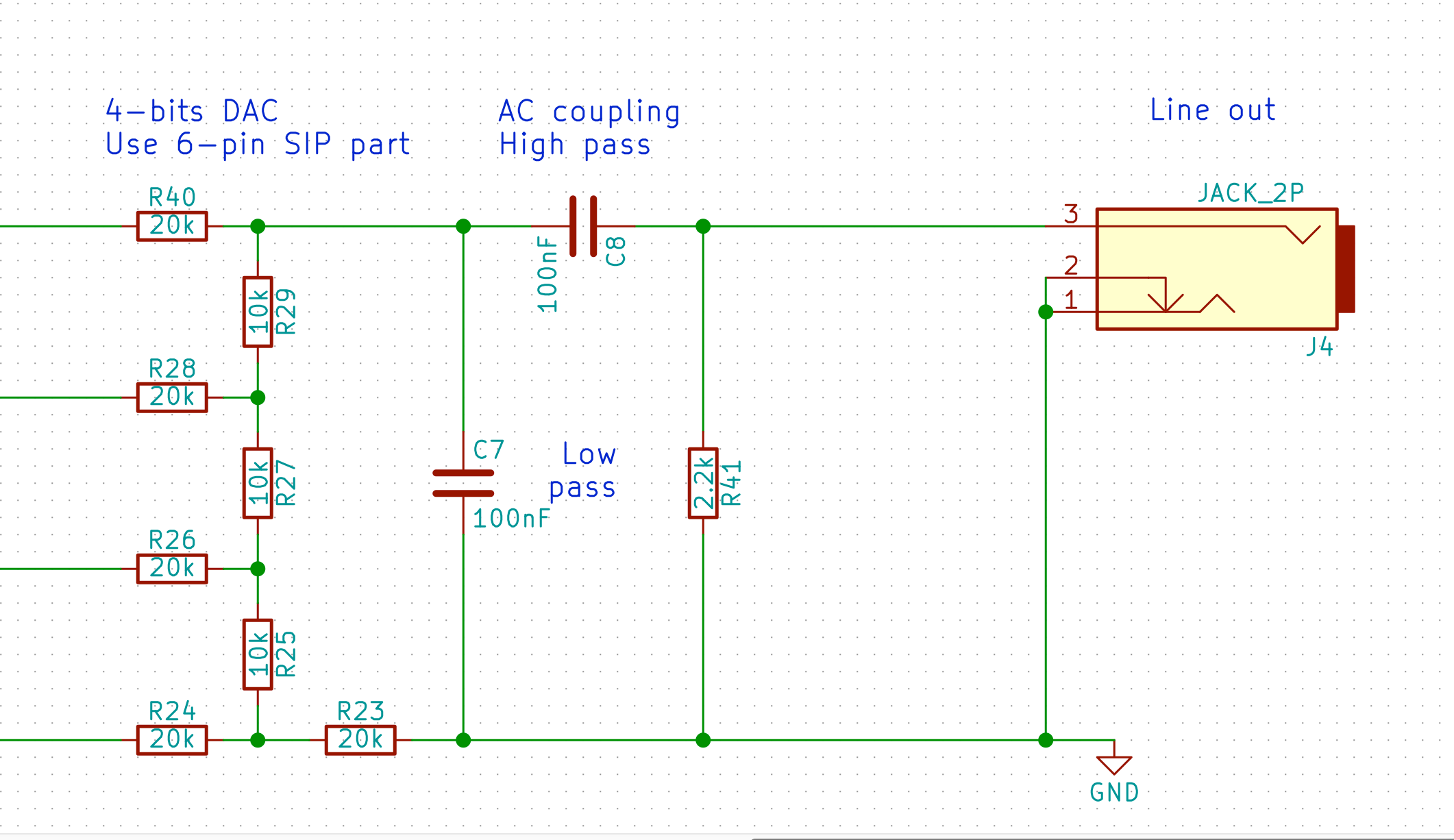
This is the circuit for the audio out part. The idea is that this is good enough to connect PC speakers to. The attenuation from logic level to line level is done by the filters. The calculated output signal should be ok:
![]()
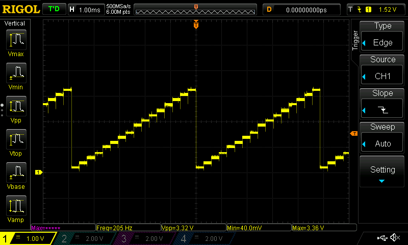
My tests run fine over the interesting audio frequency range. Here's a 555 hiding behind a pot and driving a 74HCT161 that in turn generates a 16-step sawtooth. The DAC is a 10kΩ R-2R ladder whose output gets filtered by the simple RC stage. Overall output impedance is quite high but more than suitable for the PC speakers.
![]()
Close up of the unfiltered DAC output:
![]()
All in all, it seems that I won't need an op-amp for this stage, which is what I was after.
-
Getting rid of the breadboard
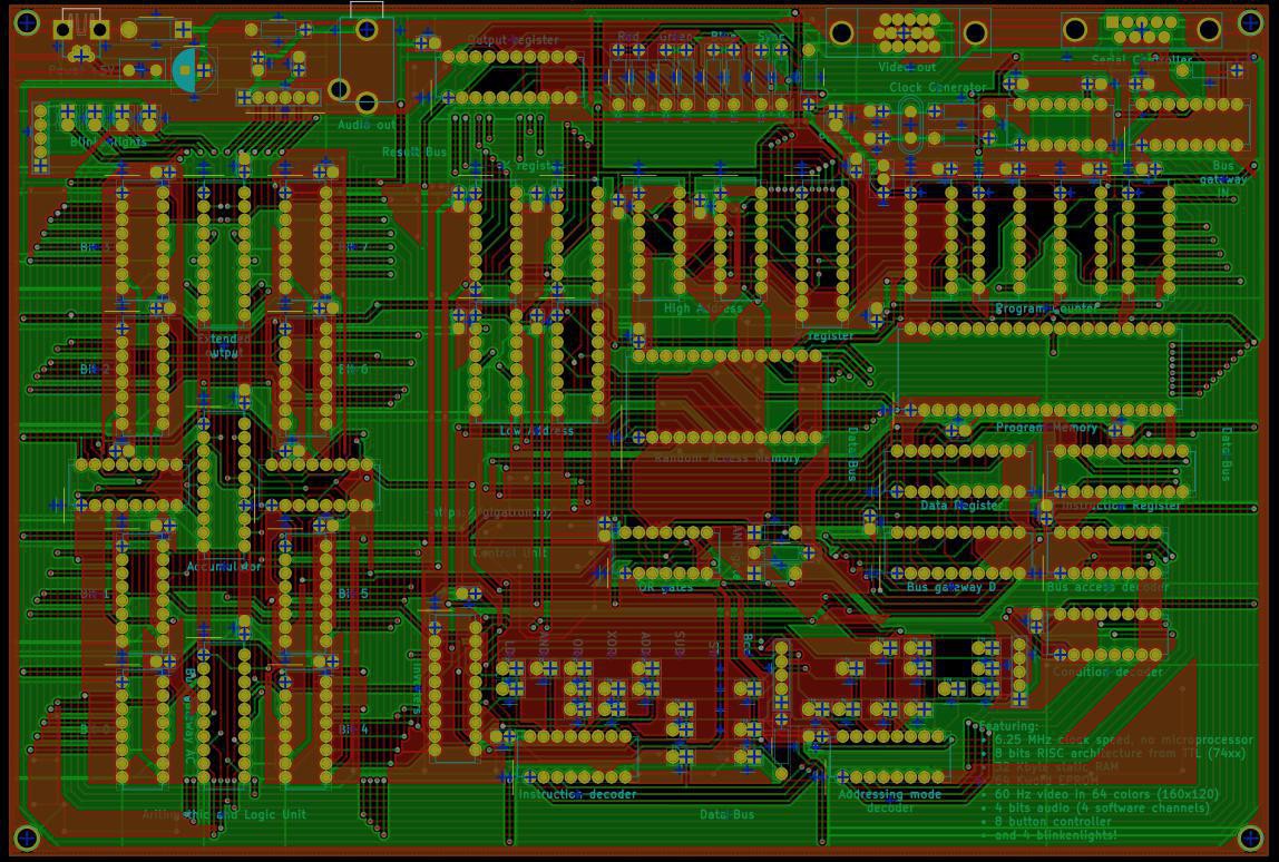
09/20/2017 at 22:39 • 0 commentsFor reliability it is better to solder everything onto a board. So I took the plunge and learnt how to use KiCad. It seems the circuit can be made on a roughly 9x6 inch board, using very relaxed spacing rules. Even if you ignore the time it takes to draw a proper schematic, making a PCB layout took a lot more time than doing the breadboard version. This surprised me a bit.
![]()
Ok, wires are flexible and that speeds things up. Traces are not flexible, and that is why they are more reliable of course. But drawing each segment manually gets harder and harder as the circuit completes. And you don't now if you have to undo major steps until you are almost done. On the other hand, in a breadboard layout you lose a lot of time on debugging wiring mistakes. You win back all that time with the EDA circuit checks, but overall the process is slower.
Perhaps my first PCB shouldn't have been a 144 component, 2 layer monster. But here it is prior to tape-out.
-
Subconsciously some logo has snuck into the layout
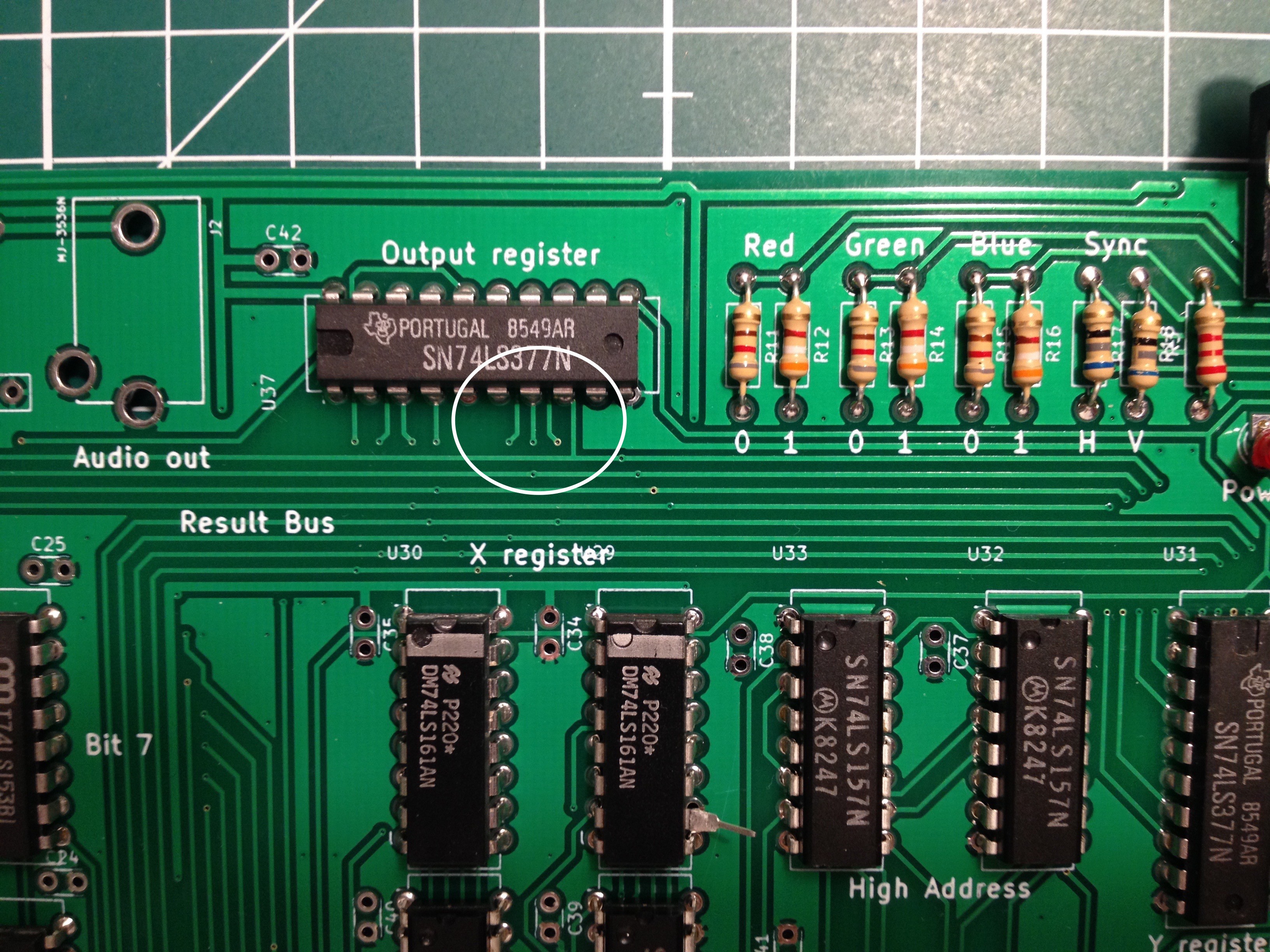
09/30/2017 at 21:50 • 2 comments![]()
Indeed, the plans to consolidate the breadboard into something more robust begin to materialise.
(And yes, U29's pin 10 isn't soldered due to a little bug.)
-
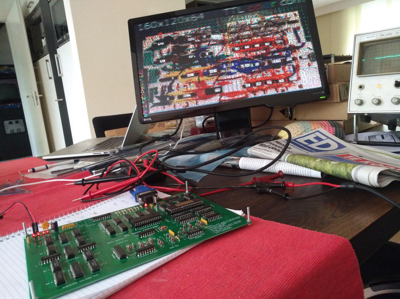
Working PCB version
10/04/2017 at 16:33 • 2 commentsThe breadboard TTL color computer has a PCB baby now. Her heart beats at 6.25 MHz. Here you see the little one sleeping and dreaming of her mom. Mother and baby are doing well. Father will be fine soon also.
![]()
-
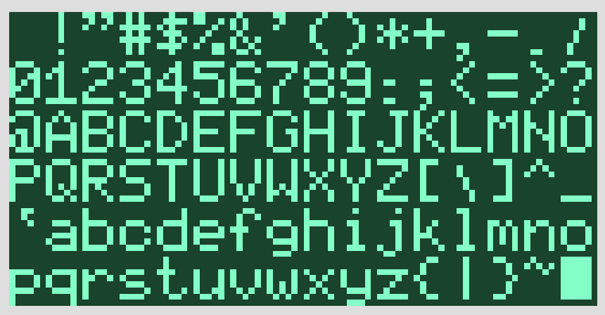
Retro font
10/13/2017 at 18:50 • 4 commentsThe resolution is good for games but 8x8 characters will still be huge. It is amazing how much variety there is among the available 5x7 and 5x8 fonts. I just have to add another one.
![]()
Tool chain: Excel --> Print as PDF --> Preview --> Save as PNG --> ImageMagick --> Scale and save as RGB --> Python. This was simpler 30 years ago.
-
G-major and scanner lights
10/15/2017 at 00:32 • 0 commentsAfter software-generated video we now also have a software generated sound playing. In four channels! And the blinkenlights are blinking, slowly getting there...
Sound and LEDs are driven by the same 8-bit extended output register which receives updates during the horizontal video sync pulse. I have split its output into 4 bits for sound and 4 bits for the LEDs. Every VGA scan line one of four independent software oscillators gets updated by the software. Every four scan lines their sum goes through the R2R DAC into the 3.5mm audio jack to the PC speakers that I picked up from a thrift store. Here I initialised the channels to play a G-major chord. I don't have a music sequencer yet, so it is just one chord. But as you can see there is a LED sequencer in place already, the music sequencer will be similar.
The extended output XOUT is just 1 extra 74273 chip that is not directly visible to the processor. It lurks on the horizontal sync for its clock and it gets its data from the accumulator. So typically it takes 3 instructions to update it. Here is how I switch off all LEDs immediately after power-on:
address
|    encoding
|    |     instruction
|    |     |    operands
|    |     |    |
V    V     V    V
0000 0000  ld   $00     # Clear AC
0001 1880  ld   $80,out # Negative flank (bit 6)
0002 18c0  ld   $c0,out # Positive flank (bit 6). This causes XOUT to be updated.
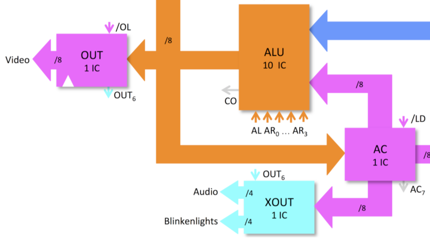
It is a simple way to get 8 additional output pins. Here it is in the block diagram:
![]()
Hardware-wise this is the second PCB build, the difference with the first board being the logic family soldered onto it: The breadboard and first PCB were using the classic 74LS series of TTL, while this board is using 74HCT chips for a change. They are completely compatible, only the video resistors needed somewhat higher values because the 74HCT outputs are always near the rails. As a result of this change, this specific board uses a lot less power: Just 80 mA for the FETs vs. 530 mA for the bipolar versions (or <0.5 Watts vs. >2.5 Watts). It should run for days on that battery pack. The difference between 1983s technology vs. 1971s...
-
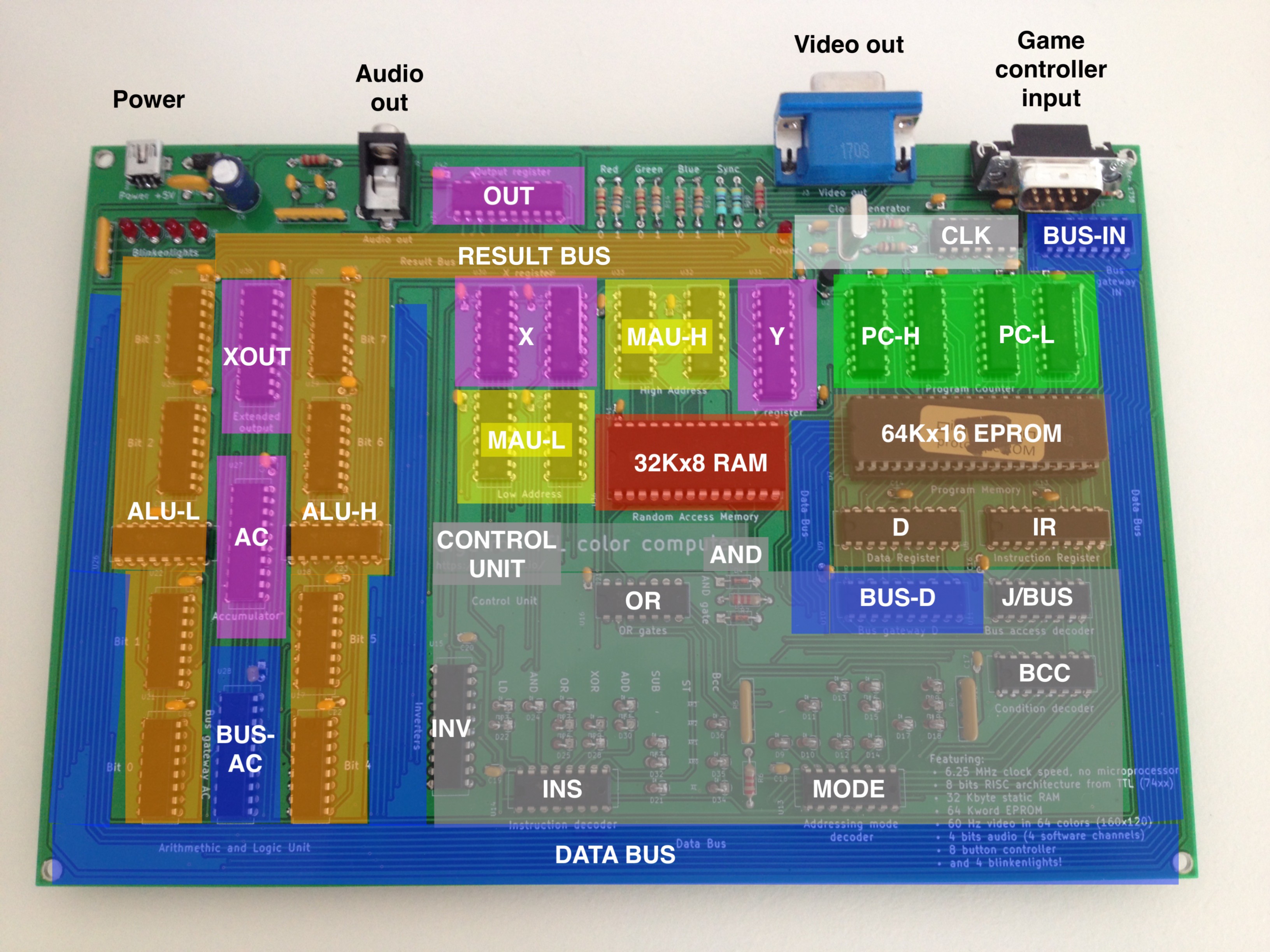
Anatomy of an 8-bits TTL microcomputer
10/15/2017 at 11:45 • 0 comments36 simple TTL chips for CPU, output and clock. A static RAM, an EPROM and a hand full of passives to make the system complete. I kept the unit coloring as in the block diagram, which in turn follows the Velleman wire colors on the breadboard version.
![]()
Gigatron TTL microcomputer
Just because! A home computer without microprocessor