 Roger
RogerThe Wankel engine rotor stool design was interesting enough to take it out of the CAD world and into the physical world. Resisting the temptation to jump straight to full-sized CNC routing, we first test the design with a scale model.
While it is possible to use a 3D printer to create the model, the laser cutter is a better choice. A laser cutter works similarly to a router: both cutting into a flat sheet of material stock. And the material can be similar as well: a laser cutter can cut wood like the CNC router.
The target material for the full-scaled project is 18mm thick plywood. Out of the material on hand for the laser cutter, the closest analogue is a sheet of 3mm thick plywood. While the smaller sheet is not made out of the same wood and it only has 3 layers, it is still a better model of behavior for full-sized plywood than a 3D printed plastic model.
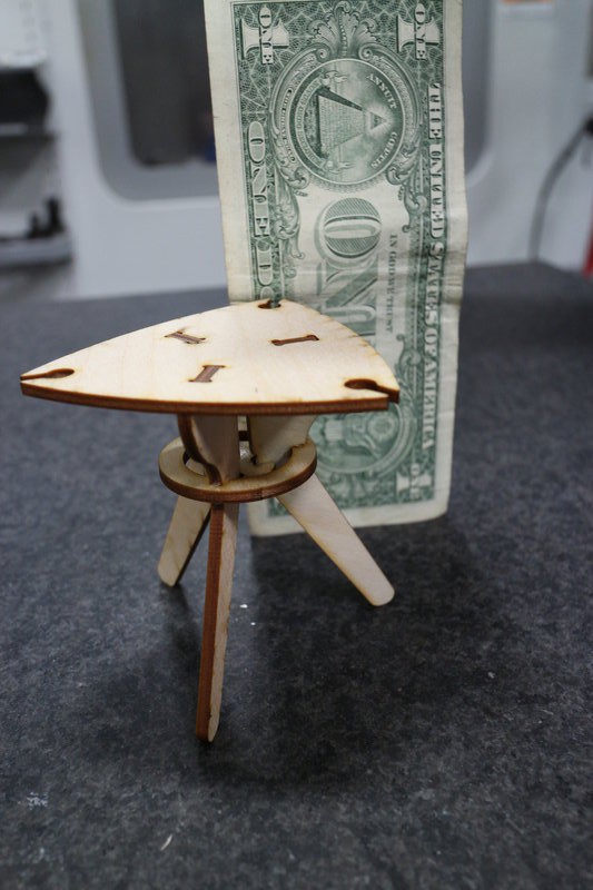
Since the small sheet is 3mm in thickness compared to 18mm of the full-sized plywood, it is easiest to make the model scale 1:6. Here is the test model with a U.S. Dollar bill for size comparison.
With the model built, we proceed to testing. The rotor stool model proved very capable holding static vertical load. We placed two blocks of aluminum stock on top and the stool didn't even quiver. We then start adding some heavy reference books on top of the aluminum. The weight of the books exposed the design flaw.
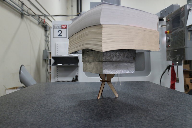
When the second book was added, the chair stood and accepted the linear vertical load without visible distortion. However, it started twisting a bit, rotating about the vertical axis, demonstrating the design's weakness in handling torsional stress. The mid-deck is capable of helping the legs resist vertical load, but it isn't helpful enough for the legs to resist side load. As a result the whole chair twists.
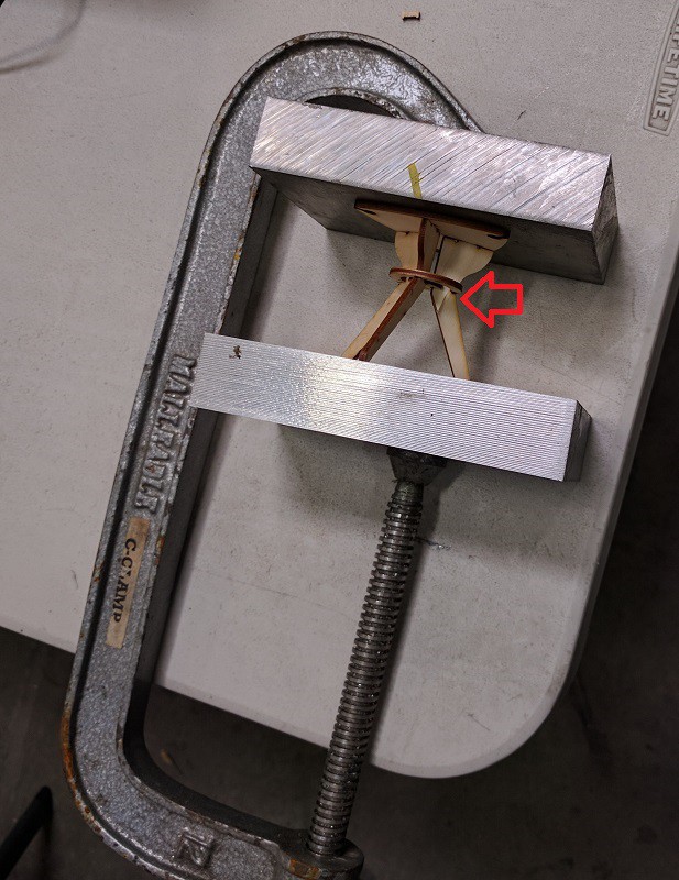
While we expect the model to hold several more books before breaking, the stack of books is starting to become unwieldy. We then moved on to a test setup with more precise control of load force. The two aluminum blocks are reused as top and bottom of a makeshift vise with a C-clamp to press them together.
As we started twisting the handle of the C-clamp, the model tried its best to stay up but eventually it started twisting. Once the vertical force was translated into a sideways force by the twist, the legs start bending sideways. Not long after the twisting started, one of the legs cracked.
The model-building and testing phase is a success: design flaws were exposed before time and money was spent on a full-sized prototype. While this design might be sufficiently strong at full scale, let's go back into CAD and iterate the design to address this structural issue.
Discussions
Become a Hackaday.io Member
Create an account to leave a comment. Already have an account? Log In.